Aerodynamic layout and design method of air-breathing hypersonic aircraft with high lift-drag ratio

An aerodynamic layout, hypersonic technology, applied in supersonic aircraft, motor vehicles, aircraft control, etc., to improve the flow separation problem, ensure wide-speed range flight performance, and efficient high-speed cruise flight capabilities.

Active Publication Date: 2022-04-12
CALCULATION AERODYNAMICS INST CHINA AERODYNAMICS RES & DEV CENT
View PDF25 Cites 5 Cited by
  • Summary
  • Abstract
  • Description
  • Claims
  • Application Information

AI Technical Summary

Problems solved by technology

The above-mentioned existing design requirements have brought great challenges to the aerodynamic layout design of this type of aircraft

Method used


Image

  • Aerodynamic layout and design method of air-breathing hypersonic aircraft with high lift-drag ratio
  • Aerodynamic layout and design method of air-breathing hypersonic aircraft with high lift-drag ratio
  • Aerodynamic layout and design method of air-breathing hypersonic aircraft with high lift-drag ratio

Examples


Embodiment 1

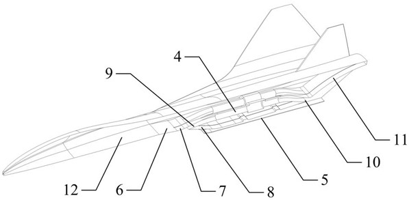
[0074] An aerodynamic layout of an air-breathing hypersonic aircraft with a high lift-to-drag ratio, including the aerodynamic layout of the airframe / inner runner; in the aerodynamic layout of the fuselage / inner runner, from front to back are the front body pre-compression surface 12 and the first-stage external compression Surface 6, secondary external compression surface 7, tertiary external compression surface 8, ram flow channel 5, first exhaust nozzle 10 and second exhaust nozzle 11, inlet splitter plate 9 is located inside secondary external compression surface 7 , the turbine runner 4 is connected in parallel above the ram runner 5 .

Embodiment 2

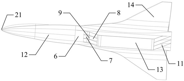
[0076] On the basis of Embodiment 1, including the aerodynamic layout of the windward side; in the aerodynamic layout of the windward side, the front end of the fuselage is the rounded head 21, followed by the front body pre-compression surface 12, the first-stage external compression surface 6, The secondary external compression surface 7, the tertiary external compression surface 8, the TBCC engine casing 13 and the tail nozzle 11, the inlet diverter plate 9 is located inside the secondary external compression surface 7, and the wings 14 are located on both sides of the rear fuselage .

Embodiment 3

[0078] On the basis of Embodiment 1 or 2, including the aerodynamic layout of the leeward side; in the aerodynamic layout of the leeward side, the shape of the longitudinal section is controlled by the fuselage ridge line 19 on the leeward side, and the shape of the transverse section is controlled by the control curve 20 of the fuselage cross section , the two sides of the fuselage are side strip wings 16 and wings 14, the two are connected front and back, and the connecting section is smoothly transitioned; Along the transition zone and the leading edge of the wing 14 are rounded, the combined wing of the side strip wing 16 and the wing 14 is located on both sides of the fuselage, and is smoothly connected with the fuselage through the wing-body fusion surface 22 .


PUM


Abstract

The invention discloses an aerodynamic layout and a design method of an air-breathing hypersonic aircraft with a high lift-drag ratio, and belongs to the field of aerodynamic layout design of aircrafts. A front body pre-compression face, a first-stage outer compression face, a second-stage outer compression face, a third-stage outer compression face, a stamping runner, a first exhaust nozzle and a second exhaust nozzle are arranged in the machine body/inner runner pneumatic layout from front to back, an air inlet channel splitter plate is located in the second-stage outer compression face, and a turbine runner is connected to the upper portion of the stamping runner in parallel. The aircraft has efficient high-speed cruise flight capability, meets the high lift requirement of the aircraft in a low-speed section, solves the problem of flow separation of high-speed wings in a low-speed take-off state, and can ensure the wide-speed-range flight performance of the aircraft.

Description

technical field [0001] The invention relates to the field of aircraft aerodynamic layout design, and more specifically, relates to an aerodynamic layout and design method of a high-lift-drag ratio air-breathing hypersonic aircraft. Background technique [0002] Hypersonic vehicles are at the forefront of the current aerospace field. Among them, hypersonic aircraft is one of the typical applications of hypersonic aircraft. This type of aircraft needs to take off and land horizontally from the ground, and cruise at high altitude and high speed for a long time. The flight airspace is large, the speed range is wide, and the aerodynamic layout design is difficult. In addition, during the flight, the aircraft is faced with a complex force / thermal environment, and the unclear cognition of the force-thermal effect further exacerbates the technical challenges of the aerodynamic layout design of this type of aircraft. [0003] Air-breathing combined power is one of the preferred powe...

Claims


Application Information

Patent Timeline
Patent Type & Authority Applications(China)
IPC IPC(8): B64C30/00B64C1/00B64C3/36B64C15/14B64F5/00
CPCY02T90/00
Inventor 陈兵刘深深韩青华曾磊桂业伟刘磊贾洪印余婧
Owner CALCULATION AERODYNAMICS INST CHINA AERODYNAMICS RES & DEV CENT
Why Eureka
Try Eureka