Construction method for constructing large and thick collapsible loess foundation by using profile steel cement soil stirring wall

A cement-soil mixing wall and collapsible loess technology, which is applied in the direction of foundation structure engineering, construction, sheet pile walls, etc., can solve the problems of insufficient density of grouting in the gaps of section steel, and reduce the amount of earthwork excavation, The construction operation is simple and the effect of improving the compactness

Pending Publication Date: 2022-04-12
信息产业部电子综合勘察研究院
View PDF5 Cites 0 Cited by
  • Summary
  • Abstract
  • Description
  • Claims
  • Application Information

AI Technical Summary

Problems solved by technology

[0004] The purpose of the present invention is to overcome the defect of insufficient grouting density in the gaps of medium-shaped steel in the prior art, and to provide a construction method for building a thick collapsible loess foundation by using a steel-cement-soil mixing wall

Method used


Image

  • Construction method for constructing large and thick collapsible loess foundation by using profile steel cement soil stirring wall
  • Construction method for constructing large and thick collapsible loess foundation by using profile steel cement soil stirring wall
  • Construction method for constructing large and thick collapsible loess foundation by using profile steel cement soil stirring wall

Examples


Embodiment 1

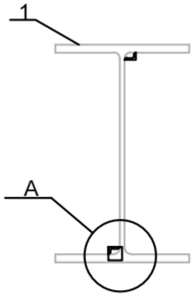
[0042] Such as figure 1 and figure 2 As shown, the present invention provides a construction method for constructing a thick collapsible loess foundation using a steel cement-soil mixing wall, which is realized by the following equipment: comprising a steel profile 1, which is an I-beam; the steel profile 1 includes an integrally formed The web 11, the first flange 12 and the second flange 13;

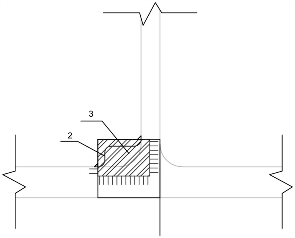
[0043] Both sides of the web 11 are provided with angle steel 2, and the angle steel 2 is fixedly connected with the first flange 12 and the web 11 or is fixedly connected with the second flange 13 and the web 11; the angle steel 2 The bottom is provided with a blocking steel plate 3, and the blocking steel plate 3 is a rectangular steel plate, and the rectangular steel plate is fully welded to the angle steel 2 and the section steel respectively.

[0044] Such as Figure 5 As shown, the construction equipment also includes a split grouting pipe 5; the body part of the split grouti...

Embodiment 2

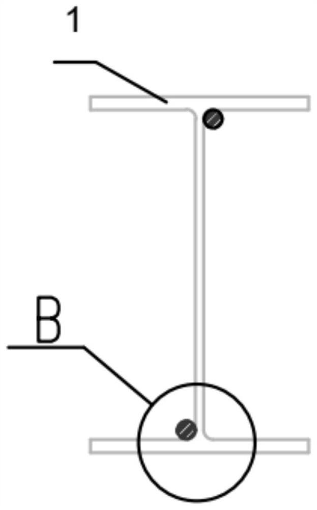
[0047] On the basis of Example 1, the combination of angle 1 and plugging steel plate can be replaced by round steel 4. For details, please refer to image 3 and Figure 4 : the round steel 4 is fixedly connected with the first flange 12 and the web 11 or is fixedly connected with the second flange 13 and the web 11; wherein the round steel 4 is a cylindrical structure.

[0048] Specifically, the above construction methods, such as Figure 6 and Figure 7 shown, including the following steps:

[0049] S1. By changing the section shape of the section steel (welding L angle steel or round steel at the position of the section steel web), and combining the construction plan of the section steel cement-soil mixing pile to complete the mixing pile, lower the section steel with the changed section into the triaxial mixing pile 7 in the groove , fill the trench with cement soil;

[0050] S2. The underground main structure is completed and reaches the design strength, and the space...


PUM


Abstract

The invention belongs to the technical field of building construction, and particularly discloses a construction method for constructing a large and thick collapsible loess foundation by using a profile steel cement soil stirring wall. Comprising section steel which is I-shaped steel; the profile steel comprises a web plate, a first flange and a second flange which are integrally formed; a first pipe reserved part is arranged on one side of the web plate, and the first pipe reserved part is fixedly connected with the web plate and the first flange; a second pipe reserved part is arranged on the other side of the web plate, and the second pipe reserved part is fixedly connected with the web plate and the second flange. The problem that existing gaps are not compact can be solved, surface water is effectively prevented from permeating into an underground structure part through profile steel pulling-out gaps, and the foundation treatment width of the loess area is reduced.

Description

technical field [0001] The invention belongs to the technical field of building construction, and in particular relates to a construction method for constructing a large-thick collapsible loess foundation by using a steel-cement-soil mixing wall. Background technique [0002] At present, the construction process of the section steel cement-soil mixing wall includes processes such as trenching, drilling with a three-axis mixer, lowering the I-beam, pulling out the I-beam, and grouting the gaps. Since the current H-shaped steel specification of the steel cement-soil mixing wall is H700*300*13*24 (20); H500*300*11*18 (15) after removal, the theoretically formed steel with a void area of ​​H500 has an area of ​​141.2-159.2cm 2 ;The maximum gap is less than 20mm, and the area after H700 type steel is pulled out is 207.5-231.5cm 2 The diameter of the corresponding minimum gap circle should be less than 25mm. After the I-shaped steel is pulled out, the cement grout is poured and f...

Claims


Application Information

Patent Timeline
Patent Type & Authority Applications(China)
IPC IPC(8): E02D5/20E02D5/46
Inventor 杨海峰李付娇赵伟张龙刘敏张江华高路皓张浩郭东欣徐光耀
Owner 信息产业部电子综合勘察研究院
Why Eureka
Try Eureka