Road construction detection supporting device
A technology for road construction and supporting devices, which is applied in the direction of supporting roof beams, pillars/brackets, mining equipment, etc. of mine roofs. It can solve problems such as inconvenient connections, inability to obtain effective and reliable connections, and inability to support tunnels. Stability, improving the efficiency of support installation, and the effect of ingenious overall design
- Summary
- Abstract
- Description
- Claims
- Application Information
AI Technical Summary
Problems solved by technology
Method used
Image

Examples
Embodiment 1
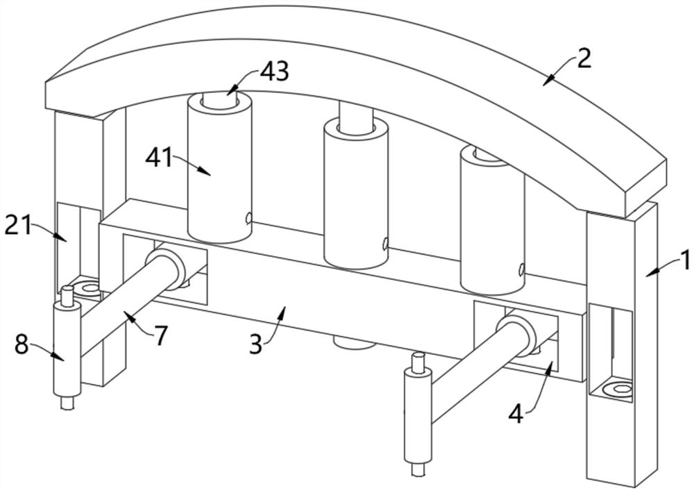
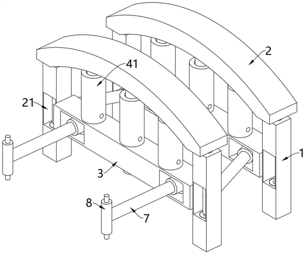
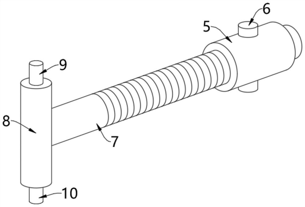
[0046] see Figure 1-Figure 5 , a road construction detection support device, including two brackets 1 arranged on the left and right sides, the two brackets 1 are fixedly connected by a connecting beam 3, and the tops of the two brackets 1 are movably provided with an arched beam 2, connected The left and right sides of the beam 3 are provided with side grooves 4, and the inside of the side groove 4 is provided with a threaded cylinder 5. The inner wall of the shaft is threadedly connected with a connecting rod 7, and the end of the connecting rod 7 is fixedly equipped with a vertical cylinder 8, and the top and bottom of the vertical cylinder 8 are respectively provided with a first insertion rod 9 and a second insertion rod 10, and the adjacent support assembly The vertical cylinder 8 is connected with the first insertion rod 9 and the second insertion rod 10 on it. When connecting, the direction of the connection rod 7 can be freely adjusted by the rotation column 6, and t...
Embodiment 2
[0058] see Image 6 with Figure 7 , on the basis of Embodiment 1, the inside of the connecting beam 3 is formed with an inner cavity 31, and the inner cavity 31 is rotated to be provided with a threaded rod 32, and the left and right sides of the outer wall of the threaded rod 32 are respectively provided with first threads with opposite rotation directions. and the second thread, the outer walls of the first thread and the second thread are respectively threaded with a first nut 33 and a second nut 34, and the opposite side of the first nut 33 and the second nut 34 is fixedly equipped with a push rod 35, The end of the push rod 35 is located in the side groove 4 and is fixedly connected with a snap ring 36, the shape of the inner wall of the snap ring 36 is coupled with the shape of the outer wall of the rotating column 6;
[0059] A driven wheel 37 is fixedly installed on the threaded rod 32, and the outer wall of the driven wheel 37 is engaged with a driving wheel 38. The...
Embodiment 3
[0062] see Figure 8 , on the basis of Embodiment 1 or Embodiment 2, several support cylinders 41 are evenly arranged on the top of the connecting beam 3. In this embodiment, three support cylinders 41 are provided, and the inner wall of the support cylinder 41 is provided with sliding plugs 42, the top of the sliding plug 42 is fixed with a support rod 43, the top of the support rod 43 extends to the outside of the support tube 41 and is fixedly connected with the arched beam 2, and the bottom of the outer wall of the support tube 41 is also provided with a one-way air intake valve 44 and manual exhaust valve 45;
[0063] When the top plate 24 and the top column 25 move upwards to drive the arched beam 2 to move upwards, the arched beam 2 can make the sliding plug 42 move upwards in the support cylinder 41 through the support rod 43. At this time, the one-way air intake valve in the support cylinder 41 44 can take in air; when the arched beam 2 is supported, since the manual...
PUM
 Abstract
Description
Claims
Application Information