
Multifunctional reinforcing steel bar laying-off device and laying-off method

A technology of multi-function and reclaiming device, applied in the field of blanking device and multi-functional steel bar blanking device, can solve the problems of large friction force of moving steel bar, not properly solved, and large error of blanking size, so as to improve the efficiency and the overall Cleverly designed, low-cost effects

Inactive Publication Date: 2017-02-22
NANJING CHEM CONSTR
View PDF8 Cites 0 Cited by
  • Summary
  • Abstract
  • Description
  • Claims
  • Application Information

AI Technical Summary

Problems solved by technology

This method of cutting steel bars requires workers to carry the steel bars to be cut to the placement platform and move the steel bars on the placement platform. The friction force is high, and the labor intensity of the workers is high. Every time a steel bar of different specifications is cut off, the size needs to be drawn and repeated verification. , the process is cumbersome, the efficiency is low, and the error of the blanking size is relatively large
Those skilled in the art try new solutions all the time, but this problem has not been properly solved

Method used


Image

  • Multifunctional reinforcing steel bar laying-off device and laying-off method

Examples


Embodiment 1

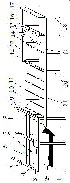
[0015] Embodiment 1: see figure 1 , a multifunctional steel bar unloading device, the unloading device includes a retrieving device, a conveying device and a cutting device, the conveying device is arranged between the retrieving device and the cutting device, and the retrieving device includes a retrieving pillar , guide rail drive motor, manipulator drive motor, vertical guide rail, horizontal guide rail, telescopic manipulator and reclaiming beam, retrieving beam 8 is installed on the upper end of reclaiming pillar 1, three vertical guide rails 5 are installed on retrieving beam 8, and horizontal guide rail 6 is installed in the vertical guide rail 5, and the guide rail driving motor 3 is installed in the middle part of the retrieving beam 8, which can drive the horizontal guide rail 6 to move in the vertical guide rail 5, and the manipulator driving motor 4 is installed on one end of the horizontal guide rail 6, two The telescopic manipulator 7 is installed in the transver...

Embodiment 2

[0016] Example 2: see figure 1 , a method for unloading a multi-functional steel bar unloading device, characterized in that: the method is as follows: 1) take out steel bar 2, use the guide rail drive motor 4 to drive the transverse guide rail 6 to move to the top of the steel bar 2, and then turn on the manipulator to drive The motor 4 makes the telescopic manipulator 7 move in the horizontal guide rail 6 to reach the stacking position of the steel bar 2, and stretches down to the steel bar 2 to grab the steel bar 2, then retracts to the original position, and then moves along the horizontal guide rail 6 to reach the conveying device Place the steel bar 2 on the rubber-covered roller by moving downward, and repeat the above steps to take out the steel bar 2; 2) For the transmission of the steel bar 2, the transmission gear box 10 is driven by the transmission motor 9 to drive the rubber-coated roller 11 to rotate , transfer the steel bar 2 placed on the rubber-covered roller...


PUM


Abstract

The invention relates to a multifunctional reinforcing steel bar laying-off device. The multifunctional reinforcing steel bar laying-off device is characterized by comprising a material taking device, a transport device and a cut-off device, wherein the transport device is arranged between the material taking device and the cut-off device. According to the technical scheme adopted by the invention, transporting and conveying of a to-be-processed reinforcing steel bar are automatic and labor intensity of workers is relieved; and meanwhile, reinforcing steel bar cut-off laying-off dimension adjustment is mechanical, simple and precise, so that laying-off efficiency is improved.

Description

technical field [0001] The invention relates to a cutting device, in particular to a multifunctional steel bar cutting device, which belongs to the technical field of building construction operations. Background technique [0002] At present, in the field of building construction, when cutting steel bars on the construction site, most of the two ends of the steel bar cutting equipment are steel bar placement platforms and steel bar storage platforms that are simply made by workers. After processing, it is collected and bundled on the storage platform and transported to the storage location. The usual construction steps are: first, use a steel ruler to mark the length of the steel bar material to be processed on the storage platform at the other end of the steel bar cutting device; then, manually move the steel bar through the steel bar cutting device to make one end of the steel bar reach the marking line on the storage platform position; the third step is to check the posi...

Claims


Application Information

Patent Timeline
IPC IPC(8): B21F11/00B21F23/00
CPCB21F11/00B21F23/007
Inventor 郭培深汪凯夏斐王雄飞笪炎炎
Owner NANJING CHEM CONSTR
Learn More