
Air inlet device and combustion system

A technology of air intake device and combustion chamber, which is applied to the charging system, fuel system, fuel supply device, etc., can solve the problems of reducing the reliability of the combustion system, easy fire in the next cycle, and easy residual high temperature exhaust gas in the pre-combustion chamber. To achieve the effect of reducing lean burn areas that are not easy to ignite

Pending Publication Date: 2022-04-12
TIANJIN UNIV
View PDF0 Cites 0 Cited by
  • Summary
  • Abstract
  • Description
  • Claims
  • Application Information

AI Technical Summary

Problems solved by technology

[0004] Furthermore, after each cycle, high-temperature exhaust gas is likely to remain in the pre-combustion chamber, which may cause ablation of the pre-combustion chamber and easy fire in the next cycle, thereby reducing the reliability of the combustion system

Method used


Image

  • Air inlet device and combustion system
  • Air inlet device and combustion system
  • Air inlet device and combustion system

Examples


Embodiment Construction

[0059] In order to make the object, technical solution and advantages of the present invention clearer, the present invention will be further described in detail below in conjunction with specific embodiments and with reference to the accompanying drawings.

[0060] The terminology used herein is for the purpose of describing particular embodiments only, and is not intended to be limiting of the present disclosure. The terms "comprising", "comprising", etc. used herein indicate the presence of stated features, steps, operations and / or components, but do not exclude the presence or addition of one or more other features, steps, operations or components.

[0061] All terms (including technical and scientific terms) used herein have the meaning commonly understood by one of ordinary skill in the art, unless otherwise defined. It should be noted that the terms used herein should be interpreted to have a meaning consistent with the context of this specification, and not be interpre...


PUM


Abstract

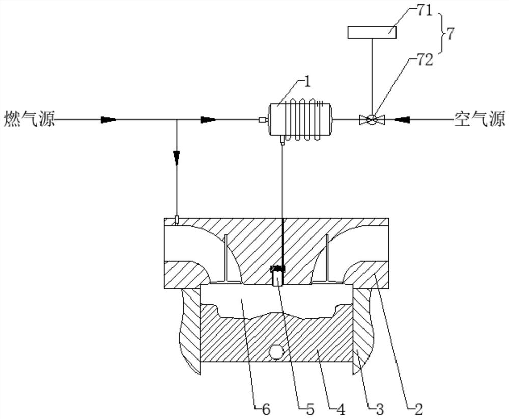
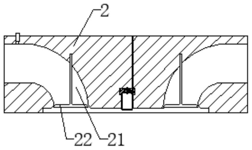
The air inlet device comprises a machine body; the piston is mounted in the machine body; the cylinder cover is installed at the opening position of the machine body, and the cylinder cover, the machine body and the piston define a first combustion chamber; the air inlet part comprises a second combustion chamber formed in the cylinder cover and communicated with the first combustion chamber; the air inlet end of the premixing tank is communicated with an air source and a fuel gas source respectively, and the exhaust end of the premixing tank is communicated with the second combustion chamber; wherein the air and the fuel gas are mixed in the premixing tank, and the mixed gas is output into the second combustion chamber. The combustion system comprises an air inlet device; a natural gas storage tank; and a compressed air storage tank; wherein the output end of the natural gas storage tank and the output end of the compressed air storage tank are respectively communicated with the premixing tank.

Description

technical field [0001] The invention relates to the technical field of internal combustion engines, in particular to an intake device and a combustion system. Background technique [0002] At present, for the pre-combustion chamber type natural gas engine, the pre-combustion chamber mostly uses fuel injectors or air intake holes to directly inject natural gas. The natural gas is mixed with the remaining air from the previous cycle in the pre-combustion chamber, and after ignition, the natural gas in the main combustion chamber is ignited. [0003] However, compared with the main combustion chamber, the volume of the pre-chamber is smaller and the structure is more complex. Therefore, it is easy to cause the problem of uneven distribution of the equivalence ratio of the pre-chamber, which in turn leads to the local existence of lean-burn and non-ignitable areas, which increases the Probability of pre-chamber misfire. At the same time, the combustion of the pre-chamber is not...

Claims


Application Information

Patent Timeline
Patent Type & Authority Applications(China)
IPC IPC(8): F02M21/04F02M21/02F02B19/12F02B43/10
CPCY02T10/12Y02T10/30
Inventor 尧命发李刚王浒郑尊清杨瑞
Owner TIANJIN UNIV
Learn More