Shock pad for automobile

A shock-absorbing pad and automobile technology, applied in the field of auto parts, can solve the problems of a single shock-absorbing pad, poor shock absorption effect, and short service life, and achieve good shock absorption effect, enhanced elastic strength, and short service life. Effect

Pending Publication Date: 2022-04-12
ANHUI ZHONGDING RUBBER PLASTIC PROD CO LTD
View PDF0 Cites 0 Cited by
  • Summary
  • Abstract
  • Description
  • Claims
  • Application Information

AI Technical Summary

Problems solved by technology

[0006] However, the structure of these shock absorbing pads is relatively simple, the allowable deformation range is small, the shock absorption effect is not good, and the service life is short. Based on this, a solution is now proposed

Method used


Image

  • Shock pad for automobile
  • Shock pad for automobile
  • Shock pad for automobile

Examples


Embodiment 1

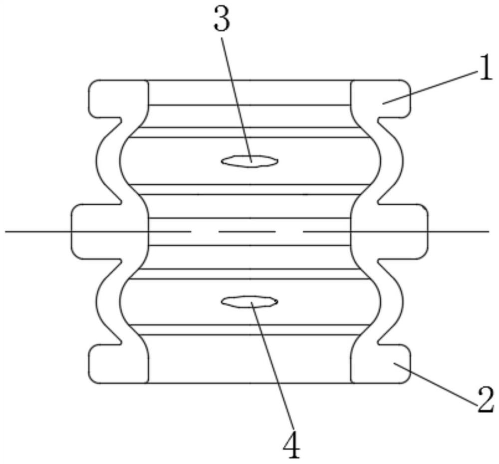
[0028] see image 3 - Figure 4 As shown, the present invention is a kind of shock absorber for automobiles, comprising shock absorbing mechanism one 1 and shock absorbing mechanism two 2, shock absorbing mechanism one 1 is positioned at the upper end of shock absorbing mechanism two 2, it is characterized in that shock absorbing mechanism one 1 It is a mirror image with the shock absorbing mechanism 2 2 , the inside and outside of the shock absorbing mechanism 2 2 are corrugated, and the shock absorbing mechanism 2 2 includes a connecting portion 21, a raised portion 22 and an end portion 23, and the raised portion 22 is located at the connecting portion 21 and the end portion 23 , the connection portion 21 is located above the end portion 23 , and the connection portion 21 , the protruding portion 22 and the inside of the end portion 23 are connected.

[0029] The integral one-piece injection molding of shock absorbing mechanism 1 and shock absorbing mechanism 2 2, the oute...

Embodiment 2

[0031] see Figure 5 As shown, the difference from the first embodiment is that: the outer surfaces of the protrusions 22 of the shock absorbing mechanism 1 and the shock absorbing mechanism 2 are provided with an annular connecting ring 5, and the through hole 3 and the through hole Two 4 all run through the connecting ring 5. Taking the shock absorbing mechanism 1 as an example, when under pressure, the shock absorbing mechanism 1 is first impacted and deformed, and the upper and lower ends of the protrusions 22 in the shock absorbing mechanism 1 are close to each other. , the whole has a tendency to expand outward, the cavity in the connecting ring 5 and the shock absorbing mechanism-1 provides sufficient deformation space, and the connecting ring 5 enhances the static stiffness, so as to avoid excessive extrusion and rupture of the raised part 22, which cannot return For the problem of spring, the connecting ring 5 provided can enhance the overall static stiffness of the s...


PUM


Abstract

The invention discloses an automobile shock pad which comprises a first shock absorption mechanism and a second shock absorption mechanism, the first shock absorption mechanism is located at the upper end of the second shock absorption mechanism, the first shock absorption mechanism and the second shock absorption mechanism form a mirror image, the second shock absorption mechanism comprises a connecting part, a protruding part and an end part, the protruding part is located between the connecting part and the end part, and the connecting part is located between the protruding part and the end part. The connecting part is located above the end part, and the interiors of the connecting part, the protruding part and the end part are communicated; most of shock pads in the prior art are of simple circular ring structures, can be formed into finished products through one-step forming, and are small in allowable deformation interval, poor in shock absorption effect and short in service life, the invention provides a process scheme, and solves the problems that the shock pads of special structures are similar to those of the shock pads in the prior art, and the production cost is low. And demolding cannot be realized in mold production.

Description

technical field [0001] The invention relates to the technical field of automobile spare parts, in particular to a shock absorbing pad for automobiles. Background technique [0002] During the operation of the car, the engine will generate huge power, and there will be bumps during driving. These are accompanied by continuous vibration, which will not only generate noise, but also greatly reduce the service life of related parts, thus affecting the driver's experience and even Safety. [0003] In the current traditional technology, shock absorbers are directly injection molded: [0004] Such as figure 1 As shown, this kind of shock absorbing pad has a simple structure and is made of PA6 material, which can be directly injection molded into finished products. This kind of shock absorbing pad has a relatively hard material, a single structure, poor rebound, and a small amount of allowable deformation. [0005] Such as figure 2 As shown, the structure of this kind of shock ...

Claims


Application Information

Patent Timeline
Patent Type & Authority Applications(China)
IPC IPC(8): F16F3/087F16F1/373
Inventor 阮宏胜夏玉洁曹春林许峰唐武亮
Owner ANHUI ZHONGDING RUBBER PLASTIC PROD CO LTD
Why Eureka
Try Eureka