
Photosensitive chip, manufacturing method thereof, laser radar and electronic equipment

A technology of laser radar and electronic equipment, which is applied in the field of semiconductors, can solve problems such as increased production difficulty, difficult to withstand temperature, and reliability issues, and achieve the effects of overcoming high production difficulty, shielding optical crosstalk, and improving sensing accuracy

Pending Publication Date: 2022-04-12
SHENZHEN FUSHI TECH CO LTD
View PDF0 Cites 0 Cited by
  • Summary
  • Abstract
  • Description
  • Claims
  • Application Information

AI Technical Summary

Problems solved by technology

[0003] At present, TOF devices on the market are usually packaged by assembling a cover on a substrate. However, the cover needs to be accurately aligned during the assembly process, which will increase the difficulty of production and increase the cost.
Moreover, the materials used to make the cover body and the glue used to attach the cover body to the substrate are difficult to withstand the high temperature during the reflow process, which easily leads to reliability problems.

Method used


Image

  • Photosensitive chip, manufacturing method thereof, laser radar and electronic equipment
  • Photosensitive chip, manufacturing method thereof, laser radar and electronic equipment
  • Photosensitive chip, manufacturing method thereof, laser radar and electronic equipment

Examples


Embodiment Construction

[0029] Embodiments of the present application are described in detail below, examples of which are shown in the drawings, wherein the same or similar reference numerals denote the same or similar elements or elements having the same or similar functions throughout. The embodiments described below by referring to the figures are exemplary, and are only for explaining the present application, and should not be construed as limiting the present application. In the description of the present application, it should be understood that the terms "first" and "second" are used for descriptive purposes only, and cannot be interpreted as indicating or implying relative importance or implicitly indicating the quantity or quantity of the indicated technical features. Order. Therefore, the technical features defined as "first" and "second" may explicitly or implicitly include one or more of said technical features. In the description of the present application, "plurality" means two or mor...


PUM


Abstract

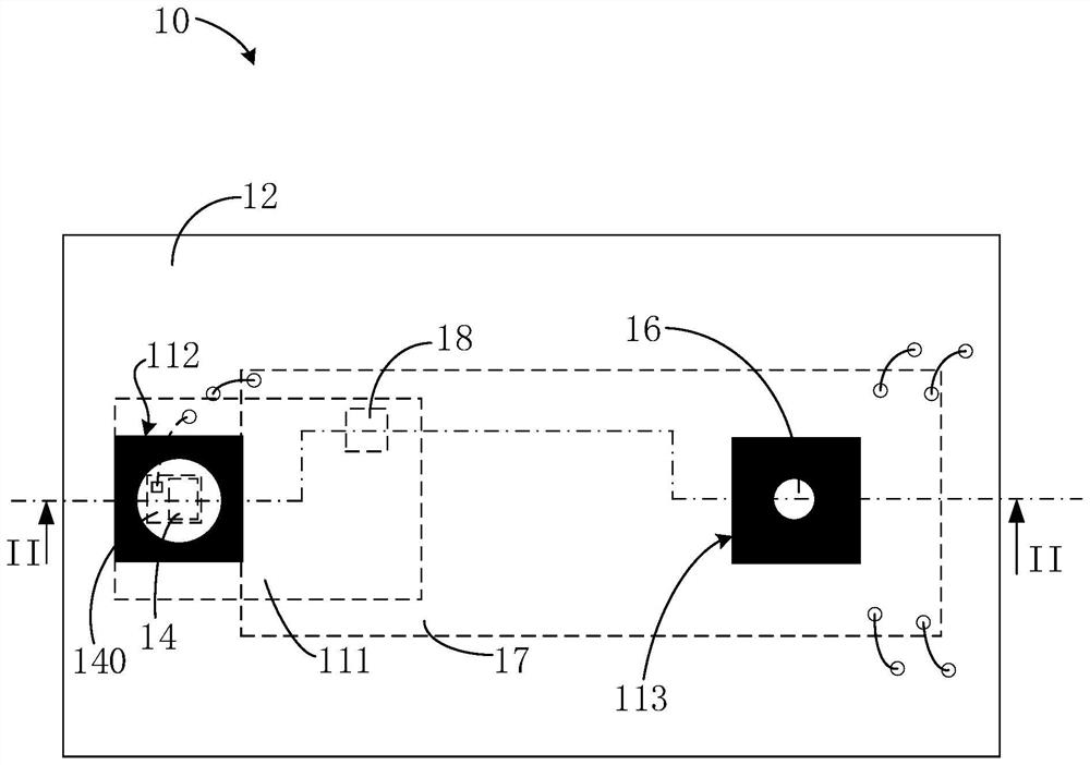
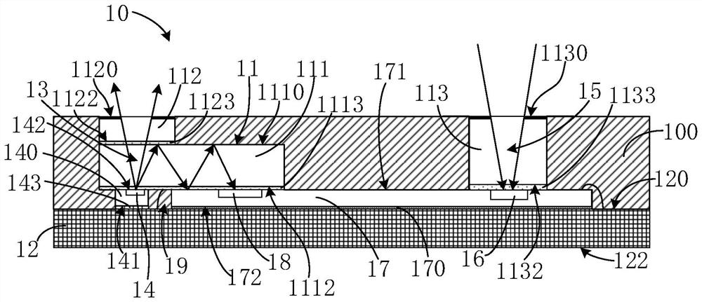
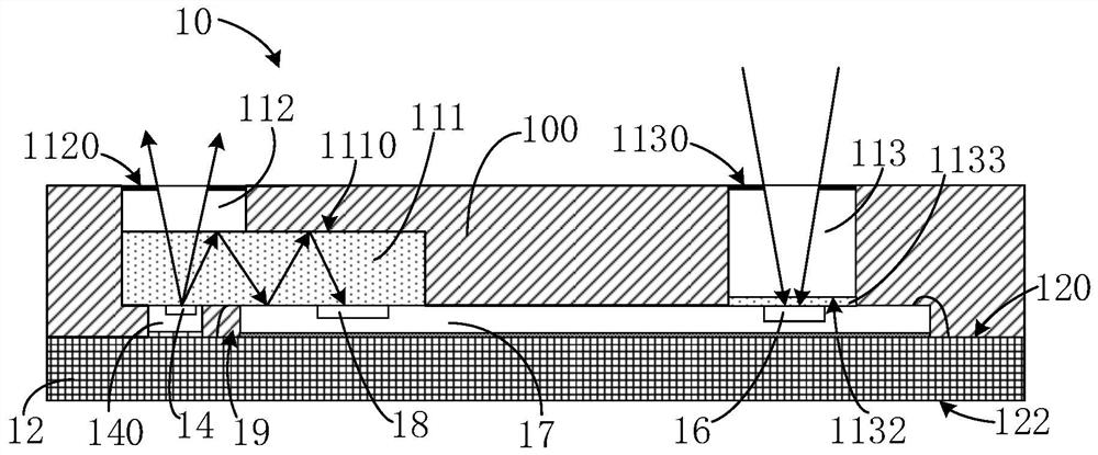
The invention provides a light sensing chip. The light sensing chip comprises a substrate, and a light-emitting bare chip, a light sensing bare chip, a first light-transmitting body, a second light-transmitting body, a third light-transmitting body and a non-light-transmitting packaging body which are arranged on the substrate. The first light-transmitting body is supported on the light-emitting die and the light-sensitive die and is disposed across the light-emitting portion of the light-emitting die and the second light-receiving portion of the light-sensitive die. The second light-transmitting body is arranged on the first light-transmitting body and corresponds to the light emitting part. The light emitting portion emits a sensing light signal to the outside through the first and second light transmissive bodies. The second light receiving part receives part of the sensing light signals transmitted by the first light transmitting body. The third light-transmitting body is arranged at the position of the first light receiving part on the photosensitive bare chip. And the first light receiving part of the photosensitive bare chip receives the returned light signal through the third light-transmitting body. The packaging body fills gaps among different components arranged on the substrate. The invention further provides a related light sensing chip manufacturing method, a laser radar and electronic equipment.

Description

technical field [0001] The present application belongs to the technical field of semiconductors, and in particular relates to an optical sensing chip and a manufacturing method thereof, as well as laser radar and electronic equipment using the optical sensing chip. Background technique [0002] A Time of Flight (TOF) device obtains three-dimensional information of an object, for example, distance information or surface depth information of an object, by measuring the time of flight of an emitted light signal in space. Due to its advantages of long sensing distance and large measurement range, it is widely used in consumer electronics, autonomous driving, AR / VR and other fields. [0003] TOF devices currently on the market are usually packaged by assembling a cover on a substrate. However, the cover needs to be accurately aligned during the assembly process, which will increase the difficulty of production and increase the cost. Moreover, the materials used to make the cover...

Claims


Application Information

Patent Timeline
IPC IPC(8): G01S7/481
Inventor 吴佳华张婉莹汪浩
Owner SHENZHEN FUSHI TECH CO LTD
Learn More