Display device and light guide plate

A technology for display devices and light guide plates, applied in identification devices, light guides, optics, etc., can solve problems such as light leakage, detachment of microstructure optical glue, and changes in refraction angles, to compensate for weakened brightness, reduce interference and extrusion, and contact area Reduced effect

Pending Publication Date: 2022-04-12
E INK HLDG INC
View PDF0 Cites 0 Cited by
  • Summary
  • Abstract
  • Description
  • Claims
  • Application Information

AI Technical Summary

Problems solved by technology

Doing so will change the angle of refraction and cause light leakage
In addition, the microstructures in areas with large bending angles or small bending radii are easily detached from the optical adhesive due to bending

Method used


Image

  • Display device and light guide plate
  • Display device and light guide plate
  • Display device and light guide plate

Examples


Embodiment Construction

[0038] A number of implementations of the present invention will be disclosed below with the accompanying drawings. For the sake of clarity, many practical details will be described together in the following description. It should be understood, however, that these practical details should not be used to limit the invention. That is, in some embodiments of the present invention, these practical details are unnecessary. In addition, for the sake of simplifying the drawings, some existing conventional structures and elements will be shown in a simple and schematic way in the drawings. Also, the thicknesses of layers and regions in the drawings may be exaggerated for clarity, and the same reference numerals denote the same elements in the description of the drawings.

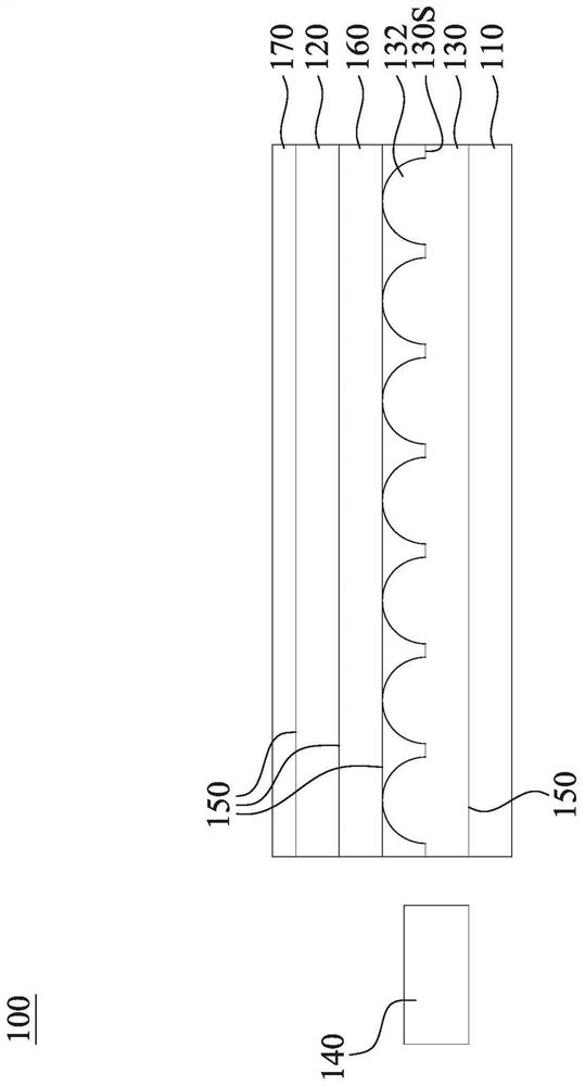
[0039] figure 1 is a cross-sectional view of a display device 100 according to an embodiment of the present invention. The display device 100 includes a reflective display panel 110 , a cover structure 120 , a l...


PUM

PropertyMeasurementUnit
thicknessaaaaaaaaaa
thicknessaaaaaaaaaa
thicknessaaaaaaaaaa

Abstract

The invention discloses a display device and a light guide plate. The display device is provided with two flat areas and a bending area located between the two flat areas. The display device comprises a reflective display panel, a cover plate structure and a light guide plate. The cover plate structure is located above the reflective display panel. The light guide plate is located between the reflective display panel and the cover plate structure. The light guide plate is provided with microstructures, the microstructures are located on the upper surface, close to the cover plate structure, of the light guide plate, the microstructures are provided with a plurality of second microstructures located in the bending area, and the sizes of the second microstructures change along with the distance between the second microstructures and the center position of the light guide plate. By adjusting the size and density of the microstructures in the bending area, the contact area between the optical cement and the microstructures can be increased or maintained so as to reduce the degumming problem. According to the display device, the probability of stripping between the microstructure and the optical cement after folding can be reduced, and interference and extrusion between the microstructure and the reflective display device can be reduced.

Description

technical field [0001] The present invention relates to a display device, in particular to a foldable display device and a light guide plate. Background technique [0002] The light guide microstructure of the light guide plate in the existing front light module is mostly suitable for non-folding design. When the display device is folded, the microstructures are easily squeezed or stretched. As a result, the angle of refraction changes and light leakage occurs. In addition, the microstructures in areas with larger bending angles or smaller bending radii are easily detached from the optical adhesive due to bending. [0003] In view of this, how to provide a light guide plate that can avoid excessive extrusion or stretching of the microstructure in the bending area, and avoid problems such as detachment of the microstructure from the optical glue, is still one of the goals that the industry needs to study urgently. one. Contents of the invention [0004] The purpose of t...

Claims


Application Information

Patent Timeline
Patent Type & Authority Applications(China)
IPC IPC(8): G02B6/00G09F9/30
Inventor 温育铨
Owner E INK HLDG INC
Why Eureka
Try Eureka