
Optical film backlight composition structure

An optical film and backlight technology, applied in the field of optical film backlight composition structure, can solve the problems of reduced service life, weak light source intensity, easy heat generation, etc., and achieve the effects of improving service life, improving heat transfer speed, and strengthening light source intensity.

Pending Publication Date: 2022-04-12
苏州灵山印刷材料有限公司
View PDF0 Cites 0 Cited by
  • Summary
  • Abstract
  • Description
  • Claims
  • Application Information

AI Technical Summary

Problems solved by technology

[0005] Aiming at the deficiencies of the prior art, the present invention provides an optical thin film backlight composition structure, which solves the problem of light loss often occurring because the backlight must use optical films such as reflective films and diffusion films to achieve the average projection of the light source. When the existing backlight module is in use, there is a problem of weak light source intensity around it, and when the above-mentioned backlight module is used for a long time, it is easy to generate heat inside, so that its service life is reduced during continuous use.

Method used


Image

  • Optical film backlight composition structure
  • Optical film backlight composition structure
  • Optical film backlight composition structure

Examples


Embodiment

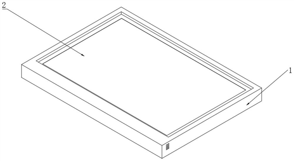
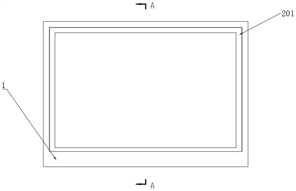
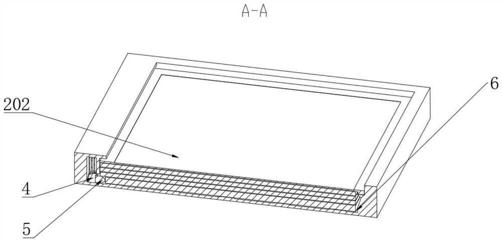
[0035] like Figures 1 to 10 As shown, an optical film backlight composition structure includes a base 1, a combination groove 6 is opened inside the base 1, a back plate is integrally arranged at the bottom of the combination groove 6, and an optical film group is arranged on the upper surface of the back plate through a first tape ring 7. 2. The LED mounting seat 10 is fixedly installed on the upper side of the backboard, and the base 1 above the LED mounting seat 10 is integrally provided with a T-shaped baffle 12. The optical film group 2 includes a reflective film layer 207 and a light guide plate layer 206 , the reflective film layer 207 is connected to the backboard through the first tape ring 7, the first tape rings 7 are respectively arranged on the upper surface of the backboard, and the LED lamp 5 is electrically installed between the LED mounting seats 10, and the LED lamp 5 is located on the reflective film layer 207 below and one side are attached to each other. ...


PUM


Abstract

The invention provides an optical thin film backlight composition structure, and relates to the technical field of optical thin films, the optical thin film backlight composition structure comprises a base, a combination groove is formed in the base, a back plate is integrally arranged at the bottom of the combination groove, an optical thin film group is arranged on the upper surface of the back plate through a first adhesive tape ring, and an LED mounting seat is fixedly mounted on one side of the upper surface of the back plate; according to the backlight module, the optical thin film set is arranged, so that diffusion of currently-emitted light can be achieved in cooperation with an LED lamp, the basic backlight light emitting function is achieved, and in order to make the light emitting effect better, through cooperation between the module and the base, the light emitting efficiency is improved; the problem that in the prior art, when an existing backlight module is used, the light source intensity on the periphery of the existing backlight module is weak is solved, the problem that the light source intensity difference on one plane is large is avoided, and a user can better display a current display picture when using the backlight module in the later period.

Description

technical field [0001] The invention relates to the technical field of optical films, in particular to an optical film backlight composition structure. Background technique [0002] The theoretical subject of optical thin films is based on the thin film optics of the interference effect of light, and studies the way light propagates in layered media. A row of light waves is irradiated on the transparent film, and two rows of light waves are respectively reflected from the upper and lower surfaces or front and rear surfaces of the film, and the two rows of coherent light waves are superimposed on each other to form an interference reaction. Optical thin films can be seen everywhere, from precision optical instruments and display devices to many applications in our lives, such as glasses, digital cameras, household appliances or banknote security technology, etc. can be called the promotion of optical thin film technology applications. [0003] However, the above-mentioned op...

Claims


Application Information

Patent Timeline
Patent Type & Authority Applications(China)
IPC IPC(8): G02B6/00G02B7/00G03B21/20G03B21/16
Inventor 陈佳金建峰
Owner 苏州灵山印刷材料有限公司
Learn More