
Triangle optical cable

An optical cable and triangular technology, applied in the field of triangular optical cables, can solve problems such as failure to work normally, poor directional impact resistance of optical cables, damage to optical cables, etc., and achieve the effects of high laying stability, high structural stability, and not easy to dislocate and deform.

Pending Publication Date: 2022-04-12
HANGZHOU FUTONG COMM TECH CO LTD
View PDF0 Cites 3 Cited by
  • Summary
  • Abstract
  • Description
  • Claims
  • Application Information

AI Technical Summary

Problems solved by technology

[0004] In order to solve the problem that the existing optical cable has poor anti-directional impact performance, and when used in some special environments, it is easy to cause damage to the optical cable due to external impact and cannot work normally. The invention provides a triangular optical cable

Method used


Image

  • Triangle optical cable
  • Triangle optical cable
  • Triangle optical cable

Examples


Embodiment

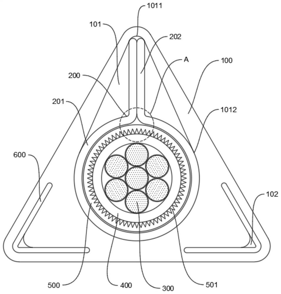
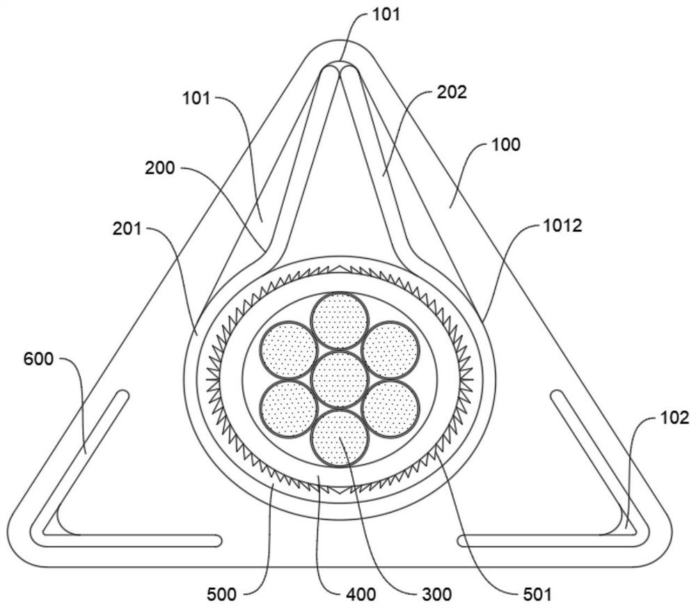
[0045] a kind of like figure 1 The triangular optical cable shown specifically includes:

[0046] The sheath 100, reinforcement cladding 200 and core wires arranged in sequence from outside to inside;

[0047] The sheath 100 is a triangular special-shaped sheath, and a drop-shaped cavity 101 is provided in the sheath 100. The tip of the drop-shaped cavity 101 faces the tip of the top of the sheath 100, and the round head 1012 faces the side opposite to the tip;

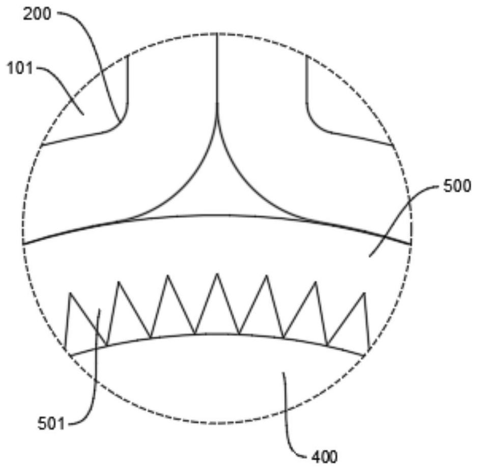
[0048] The reinforcement cladding 200 is composed of a support rib 202 and an annular cladding 201. The annular cladding 201 is arranged on the round head 1012 of the drop-shaped cavity 101 and is against the inner wall of the round head 1012 of the drop-shaped cavity 101. connected, and it is provided with an opening toward the tip 1011 of the drop-shaped cavity 101, and both ends of the opening extend toward the tip 1011 of the drop-shaped cavity 101 to form support ribs 202, and the two support ribs 202 are formed...


PUM


Abstract

The invention belongs to the field of optical cables and particularly relates to a triangular optical cable. The cable comprises a sheath, a reinforcer wrapping layer and a core wire which are sequentially arranged from outside to inside, the sheath is a triangular special-shaped sheath, a cavity is formed in the sheath, the upper end of the cavity faces the tip end of the top of the sheath, and the lower end of the cavity faces the side edge opposite to the tip end; the reinforcing part cladding is composed of supporting ribs and an annular cladding, the annular cladding is arranged at the lower end of the cavity and abuts against the inner wall of the lower end of the cavity, an opening is formed in the annular cladding in the direction facing the upper end of the cavity, and the two ends of the opening extend towards the upper end of the cavity to form the supporting ribs. The two formed supporting ribs extend to the upper end of the cavity and abut against the inner wall of the upper end of the cavity. The core wire comprises a plurality of optical fibers fixed by a belting layer, and each optical fiber is an optical fiber bundle formed by a single optical fiber or a plurality of optical fibers; and the belting layer is used for accommodating and fixing the optical fiber. Through the special structural design, the vertical impact resistance of the optical cable is remarkably improved.

Description

technical field [0001] The invention belongs to the field of optical cables, in particular to a triangular optical cable. Background technique [0002] Optical cable is a kind of communication optical cable with rapid development in modern times, which is widely used in various industries and fields. In some special fields, there are often some specific requirements for optical cables, such as optical cables used in river basins, sea areas or similar humid places need to have good waterproof and moisture-proof performance, and it is necessary to strengthen the waterproof and moisture-proof performance of ordinary optical cables. Water seepage and aging damage; and in areas with strong winds such as plateaus and plains, it is necessary to strengthen the windproof and torsional performance of the optical cable to avoid twisting and breaking under the influence of the natural environment. [0003] For optical cables, it is generally required to have good pressure resistance an...

Claims


Application Information

Patent Timeline
Patent Type & Authority Applications(China)
IPC IPC(8): G02B6/44
Inventor 周永明
Owner HANGZHOU FUTONG COMM TECH CO LTD
Learn More