
Temperature control method for optical fiber preform acceleration mold base, computer medium and computer

A temperature control method and optical fiber preform technology, applied in the direction of temperature control, control/regulation system, non-electrical variable control, etc., can solve the problem of long response time of water bath, untimely adjustment of mold base temperature, and coating diameter of optical fiber preform. the reduction of the compliance rate, etc., to achieve the effect of shortening the response time and improving the compliance rate

Active Publication Date: 2022-04-12
江苏南方光纤科技有限公司
View PDF15 Cites 0 Cited by
  • Summary
  • Abstract
  • Description
  • Claims
  • Application Information

AI Technical Summary

Problems solved by technology

[0006] For this reason, the technical problem to be solved by the present invention is to overcome the problem that the response time of the water bath box of the mold temperature PID system in the prior art is too long, and the mold base temperature is not adjusted in time, which causes the problem that the compliance rate of the coating diameter of the optical fiber preform is reduced. A method for controlling the temperature of an optical fiber preform speed-up mold base with a high compliance rate, a computer medium and a computer

Method used


Image

  • Temperature control method for optical fiber preform acceleration mold base, computer medium and computer
  • Temperature control method for optical fiber preform acceleration mold base, computer medium and computer

Examples


Embodiment Construction

[0031] The present invention will be further described below in conjunction with the accompanying drawings and specific embodiments, so that those skilled in the art can better understand the present invention and implement it, but the examples given are not intended to limit the present invention.

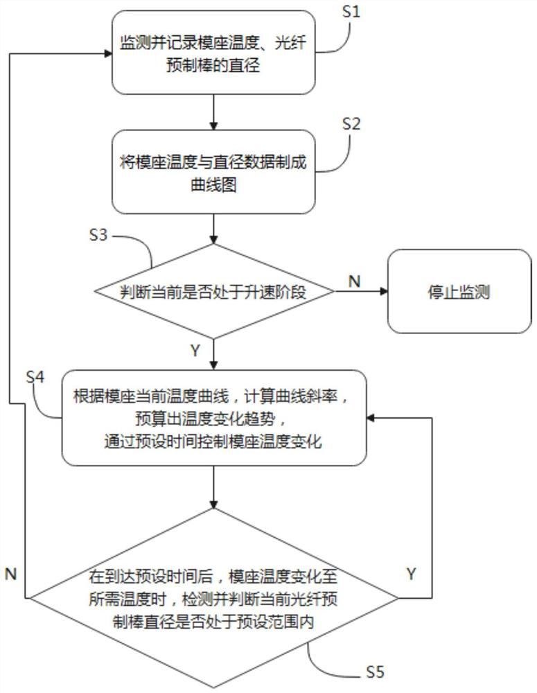
[0032] In some embodiments, referring to figure 1 As shown, a method for controlling the temperature of an optical fiber preform speed-up mold base of the present invention comprises the following steps:

[0033] S1: Monitor and record the mold base temperature and the diameter of the optical fiber preform;

[0034] S2: Make a graph of the mold base temperature and diameter data;

[0035] S3: Judging whether it is currently in the speed-up stage, if not, stop monitoring, if so, execute step S4;

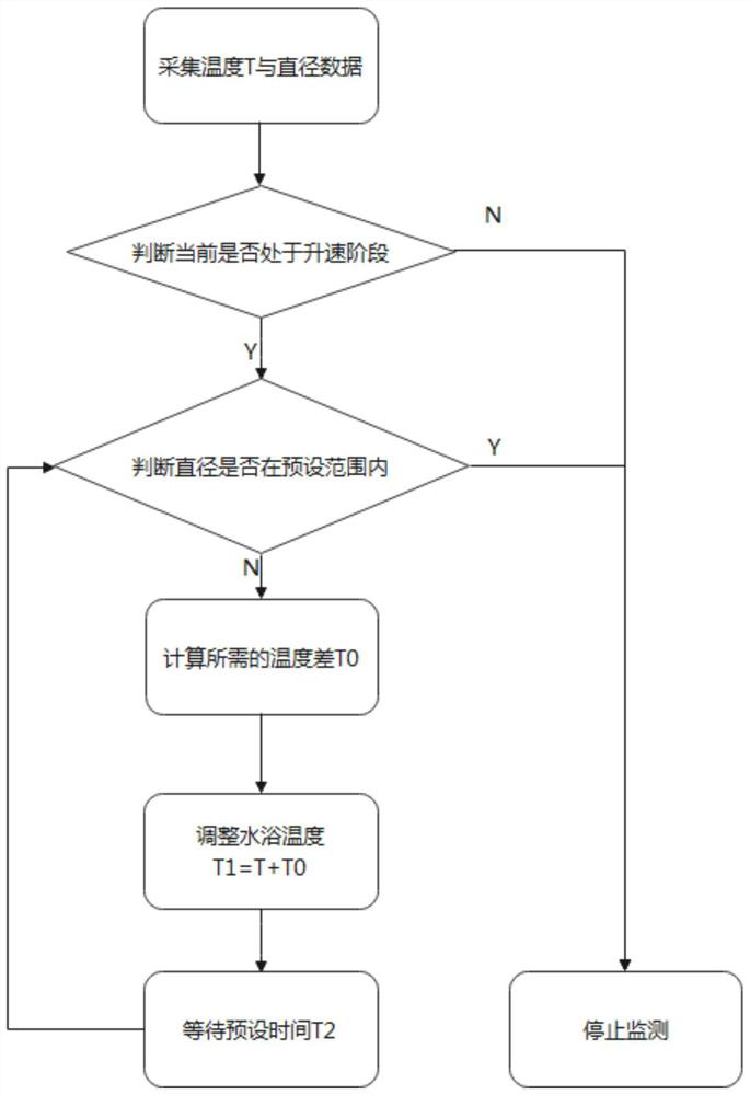
[0036] S4: According to the current temperature curve of the mold base, calculate the slope of the curve, estimate the temperature change trend, and control the temperature change of th...


PUM


Abstract

The invention relates to a temperature control method for an optical fiber preform acceleration mold holder, a computer medium and a computer, and the temperature control method for the optical fiber preform acceleration mold holder comprises the following steps: S1, monitoring and recording the temperature of the mold holder and the diameter of an optical fiber preform; s2, making a curve graph according to the temperature and diameter data of the die holder; s3, judging whether the current state is in a speed increasing stage or not; s4, according to the current temperature curve of the die holder, the curve slope is calculated, the temperature change trend is estimated, and the temperature change of the die holder is controlled through preset time; and S5, detecting and judging whether the diameter of the current optical fiber preform is in a preset range or not when the temperature of the die holder is changed to the required temperature after the preset time is up. According to the method for controlling the temperature of the speed-increasing die holder of the optical fiber preform, the temperature change trend is estimated according to the curve slope calculated according to the current curve graph, the temperature change of the die holder is controlled, the response time is shortened, and the temperature of the die holder is adjusted in time, so that the standard-reaching rate of the coating diameter of the optical fiber preform is increased.

Description

technical field [0001] The invention relates to the technical field of optical fiber preform production, in particular to a method for controlling the temperature of an optical fiber preform speed-up mold base, a computer medium and a computer. Background technique [0002] During the production process of the optical fiber preform, it needs to go through three stages of speed up, steady speed, and end of the rod. In these three stages, the temperature of the mold base needs to be monitored and adjusted respectively to ensure that the diameter of the optical fiber preform reaches the standard. [0003] In the prior art, the automatic adjustment of the mold base temperature through the mold temperature PID system is only applicable to the steady speed stage. For the case where the coating diameter changes too fast in the speed up stage, the existing mold temperature PID system automatically adjusts the temperature. The response time of the mold base water bath is too long, wh...

Claims


Application Information

Patent Timeline
IPC IPC(8): G05D23/20C03B37/012
CPCY02P40/57
Inventor 施明杰黄均亮卜惠华葛文金
Owner 江苏南方光纤科技有限公司
Learn More