Channel flow measurement method based on scale effect of central cylindrical rectangular groove

A technology of central cylinder and scale effect, applied in the field of channel flow measurement method, can solve the problems that can not be measured by channel flow, cannot be used to predict the flow of the central cylindrical rectangular slot, and the flow prediction method of the central cylindrical rectangular slot, etc. Water utilization efficiency, improving numerical calculation accuracy and calculation efficiency, and avoiding the effect of backwater waste

Pending Publication Date: 2022-04-12
NANCHANG INST OF TECH
View PDF2 Cites 2 Cited by
  • Summary
  • Abstract
  • Description
  • Claims
  • Application Information

AI Technical Summary

Problems solved by technology

However, in the prior art, there is no method for predicting the flow rate of the central cylindrical rectangular groove by means of numerical experiments.
Chinese patent CN201910015788.6 discloses a method for predicting the critical submergence depth of a wet chamber pump station through CFD. In this patent, CFD is used to predict the critical submergence depth of the pump station, but the method cannot be used to predict the flow rate of the central cylindrical rectangular tank. CN201811325431.X discloses a method for predicting the flow rate of large-scale low-lift water pumps. In this patent, the flow rate of large-scale low-lift water pumps is predicted by using CFD combined with the differential pressure flow measurement method. Similarly, the method cannot be used for the channel flow test of this application

Method used


Image

  • Channel flow measurement method based on scale effect of central cylindrical rectangular groove
  • Channel flow measurement method based on scale effect of central cylindrical rectangular groove
  • Channel flow measurement method based on scale effect of central cylindrical rectangular groove

Examples


Embodiment Construction

[0039] The present invention will be further described below in conjunction with the accompanying drawings.

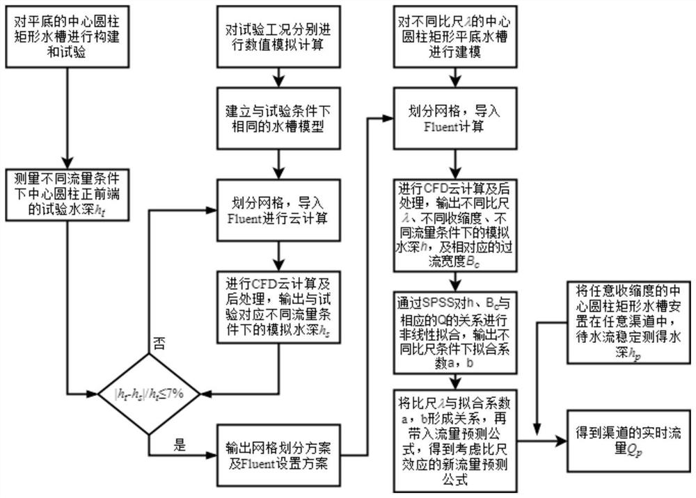
[0040] The flow chart of the channel flow measurement method based on the scale effect of the central cylindrical rectangular groove in this embodiment is as follows figure 1 As shown, the specific steps are as follows:

[0041] Step 1: Establish a physical test model of the central cylindrical rectangular groove and conduct a physical model test. When the water flow is stable, collect the height of the submerged water depth of the front end of the cylinder;

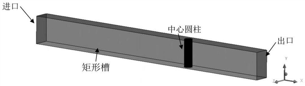
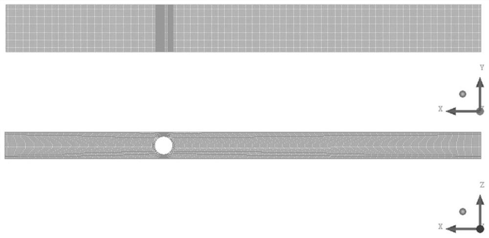
[0042] In the physical model, the material of the central cylindrical rectangular trough model is transparent plexiglass, the bottom of the rectangular trough is placed horizontally, the flow section of the rectangular trough is rectangular, the bottom width is 17cm, the height is 30cm, and the diameter of the central cylinder is 11.4cm. The shrinkage ratio was 0.670.

[0043] The length of the rectangular tank...


PUM


Abstract

The invention discloses a channel flow measurement method based on the scale effect of a central cylindrical rectangular groove, and the method comprises the steps: carrying out the verification of a numerical simulation method, carrying out the numerical calculation and physical testing of the rectangular groove, and carrying out the analysis and comparison of a large amount of data, and obtaining a correct and reasonable CFD setting method. Numerical simulation is carried out on central cylindrical rectangular grooves of different geometric scales through the obtained CFD setting method, after calculation is completed, water depths and contraction overflowing widths under different geometric scales, contraction degrees and flow conditions are output, and data processing is carried out through SPSS and Origin to obtain a new flow prediction formula. During CFD numerical calculation, cloud calculation is introduced to improve the calculation precision and efficiency of CFD. When the channel flow is measured, the central cylindrical rectangular groove with the corresponding scale is arranged in the channel according to the size of the channel, and after the water flow is stable, the measured water depth and the corresponding scale are substituted into a flow formula, so that the real-time channel flow can be obtained. The channel flow can be accurately tested, operation is convenient, manufacturing is low in cost, and adaptability is high.

Description

technical field [0001] The invention relates to a channel flow measurement method based on the scale effect of a central cylindrical rectangular groove, which belongs to the technical field of water conservancy engineering. Background technique [0002] Water management in irrigation areas is crucial to the construction of irrigation areas. Water management in irrigation areas mainly refers to the reasonable adjustment and distribution of irrigation water volume, flow and irrigation time, so as to maximize the benefits of irrigation and drainage projects, effectively use irrigation water sources, improve irrigation water quality and efficiency, and promote agriculture. Stable and high yield. In recent years, the state has vigorously led the intelligent and intelligent development of irrigation areas. The inherent meaning is to reform the traditional operation methods of irrigation areas through advanced technology. Therefore, it is particularly important to accurately test t...

Claims


Application Information

Patent Timeline
Patent Type & Authority Applications(China)
IPC IPC(8): G06F30/28G06F30/10G06F111/10G06F113/08G06F119/14
Inventor 姚莉朱晓明金鹏涛叶晓慧李金波陈浩顾信钦周意恒刘志峰张思金石先罗任长江斯静吴建华
Owner NANCHANG INST OF TECH
Why Eureka
Try Eureka