Chip mounting method

A chip mounting and chip technology, which is applied in the field of semiconductor packaging, can solve the problems of overflowing glue, insufficient silver glue coverage, and insufficient thickness of climbing glue, etc., and achieve the effects of uniform thickness, increased chip production capacity, and consistent coverage area

Pending Publication Date: 2022-04-12
JCET GROUP CO LTD
View PDF0 Cites 0 Cited by
  • Summary
  • Abstract
  • Description
  • Claims
  • Application Information

AI Technical Summary

Problems solved by technology

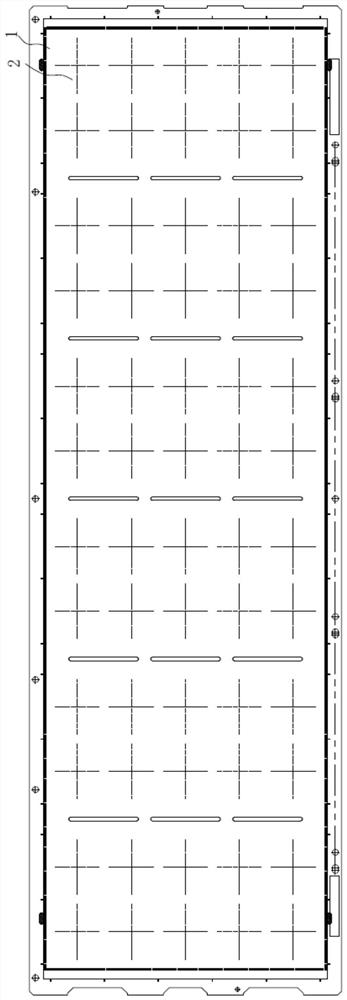
[0006] The purpose of the present invention is to provide a chip mounting method, which is used to significantly improve the problems of insufficient coverage of silver glue in the chip loading area of ​​the lead frame, insufficient thickness of glue climbing, and overflow of glue.

Method used


Image

  • Chip mounting method
  • Chip mounting method
  • Chip mounting method

Examples


Embodiment Construction

[0040] In order to make the object, technical solution and advantages of the present invention clearer, the present invention will be further described in detail below in conjunction with the embodiments and accompanying drawings. It should be understood that the specific embodiments described here are only used to explain the present invention, not to limit the present invention.

[0041] In the description of the present invention, it should be noted that the terms "center", "upper", "lower", "left", "right", "vertical", "horizontal", "inner", "outer" etc. The indicated orientation or positional relationship is based on the orientation or positional relationship shown in the drawings, and is only for the convenience of describing the present invention and simplifying the description, rather than indicating or implying that the referred device or element must have a specific orientation, or in a specific orientation. construction and operation, therefore, should not be constr...


PUM

PropertyMeasurementUnit
thicknessaaaaaaaaaa
thicknessaaaaaaaaaa
thicknessaaaaaaaaaa

Abstract

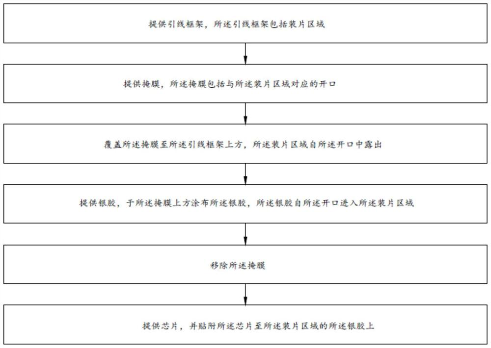
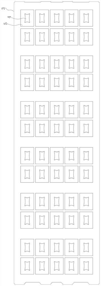
The invention provides a chip mounting method, and the method comprises the steps: providing a lead frame which comprises a chip mounting region; providing a mask, wherein the mask comprises an opening corresponding to the loading area; covering the mask to the upper part of the lead frame, wherein the chip mounting area is exposed from the opening; silver colloid is provided, the upper portion of the mask is coated with the silver colloid, and the silver colloid enters the chip loading area from the opening; the mask is removed; providing a chip, and attaching the chip to the elargol in the chip mounting area; wherein the silver content of the silver colloid ranges from 80% to 90%, and the viscosity of the silver colloid ranges from 40000 cps to 80000 cps; the opening comprises a plurality of mutually connected side edges, and each side edge is bent or bent towards the interior of the opening.

Description

technical field [0001] The invention belongs to the technical field of semiconductor packaging, in particular to a chip mounting method. Background technique [0002] The existing chip placement methods mainly include: through the dispensing mechanism of the placement machine and the vacuum and pressure device, the silver glue in the rubber tube is dotted or drawn to the chip loading area of ​​the lead frame; The suction nozzle on the head, through the internal vacuum adsorption, peels and picks up the chips one by one from the wafer; then releases the suction nozzle on the welding head of the placement machine through the internal vacuum, and places the chips adsorbed on the suction nozzle on the Above the silver glue in the chip loading area of ​​the frame, the pressure and time are controlled by the welding head of the placement machine, so that the silver glue overflows around the chip, so that the chip and the lead frame are fixedly connected through the silver glue. ...

Claims


Application Information

Patent Timeline
Patent Type & Authority Applications(China)
IPC IPC(8): H01L21/48
Inventor 贺亢翟海峰张旭东濮虎
Owner JCET GROUP CO LTD
Why Eureka
Try Eureka