MPPT control algorithm transient real-time simulation method and device based on FPGA
A technology of control algorithm and real-time simulation, which is applied in general control systems, design optimization/simulation, control/regulation systems, etc., and can solve problems such as real-time transient simulation of distributed power generation systems that are difficult to implement detailed models
- Summary
- Abstract
- Description
- Claims
- Application Information
AI Technical Summary
Problems solved by technology
Method used
Image
Examples
Embodiment 1
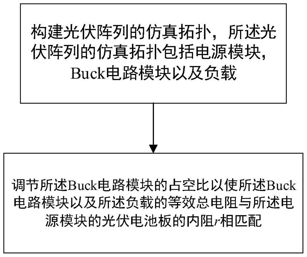
[0060] The present invention provides a kind of FPGA-based MPPT control algorithm transient state real-time emulation method, specifically comprises the following steps:
[0061] Construct the simulation topology of photovoltaic array, the simulation topology of described photovoltaic array comprises power supply module, Buck circuit module and load;
[0062] The duty cycle of the Buck circuit module is adjusted so that the equivalent total resistance of the Buck circuit module and the load matches the internal resistance r of the photovoltaic panel of the power module.
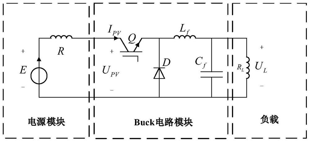
[0063] Further, it is necessary to match the equivalent load with the internal resistance of the photovoltaic cell. . Photovoltaic arrays usually match the load impedance with an external power conversion circuit to achieve maximum power output. image 3 As shown, the present invention connects the photovoltaic panel to the load resistance through the Buck circuit, and the FPGA processes the detected power...
Embodiment 2
[0104] The embodiment of the present invention provides a kind of FPGA-based MPPT control algorithm transient real-time simulation device, comprising:
[0105] Topology building module: used to construct the simulation topology of the photovoltaic array, the simulation topology of the photovoltaic array includes a power module, a Buck circuit module and a load;
[0106] Duty cycle adjustment module: used to adjust the duty cycle of the Buck circuit module so that the equivalent total resistance of the Buck circuit module and the load matches the internal resistance r of the photovoltaic panel of the power module.
Embodiment 3
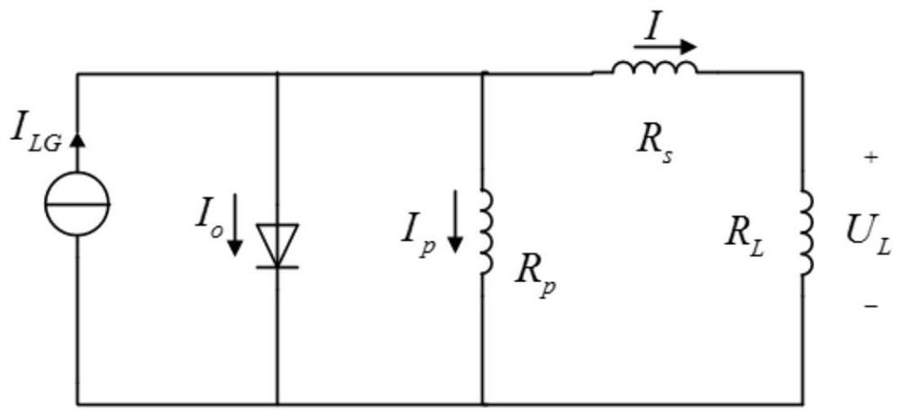
[0108] combine figure 2 as well as image 3 , in the embodiment provided by the present invention, the initial value of the duty cycle is given as 0.5 (the counter value is 200), and then a disturbance in the positive direction is given to perform functional verification on the overall design module on the modelsim software platform, u1 and i1 is the collected u pv and i pv , data2t is the power output by the photovoltaic panel at the current moment, data1t is the output power at the previous moment, d3=|data2t-data1t|, Duty ratio ddt=α*400, duty ratio difference quotient=ΔD=d3 / d4, considering that the base number is 400, taking into account the calculation accuracy and speed, here the step size ΔD is calculated as an approximate integer.
[0109] When the rising edge of the second pulse arrives, it is calculated that data2=56>data1=22, and the change in duty cycle is ΔD=214-201=13>0. At this time, the system judges that it is a disturbance in the positive direction, and ...
PUM
 Abstract
Description
Claims
Application Information
 - R&D
- Intellectual Property
- Life Sciences
- Materials
- Tech Scout
- Unparalleled Data Quality
- Higher Quality Content
- 60% Fewer Hallucinations
Browse by: Latest US Patents, China's latest patents, Technical Efficacy Thesaurus, Application Domain, Technology Topic, Popular Technical Reports.
© 2025 PatSnap. All rights reserved.Legal|Privacy policy|Modern Slavery Act Transparency Statement|Sitemap|About US| Contact US: help@patsnap.com


