Protection circuit of power tube, power supply protection chip and equipment

A technology for protecting circuits and power tubes, applied in the field of circuits, can solve problems such as burnout of P-type power tubes and large drain-source voltage, and achieve the effect of protection and safety

Pending Publication Date: 2022-04-12
SHANGHAI AWINIC MICROELECTRONIC TECH CO LTD
View PDF0 Cites 3 Cited by
  • Summary
  • Abstract
  • Description
  • Claims
  • Application Information

AI Technical Summary

Problems solved by technology

However, this solution does not limit the output voltage, the drain-source voltage may still be large, and there is a risk of high power in high-current applications, which may cause the P-type power tube to be burned out

Method used


Image

  • Protection circuit of power tube, power supply protection chip and equipment
  • Protection circuit of power tube, power supply protection chip and equipment
  • Protection circuit of power tube, power supply protection chip and equipment

Examples


Embodiment Construction

[0030] The solutions in the embodiments provided in the present application will be described below with reference to the drawings in the present application.

[0031] The terms "first" and "second" in the embodiments of the present application are used for description purposes only, and cannot be understood as indicating or implying relative importance or implicitly indicating the quantity of indicated technical features. Thus, a feature defined as "first" and "second" may explicitly or implicitly include one or more of these features.

[0032] First, some technical terms involved in the embodiments of the present application are introduced.

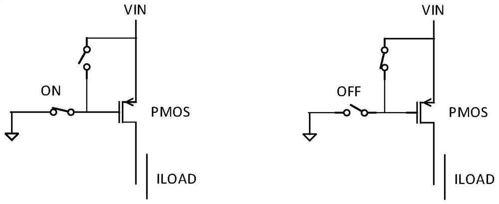
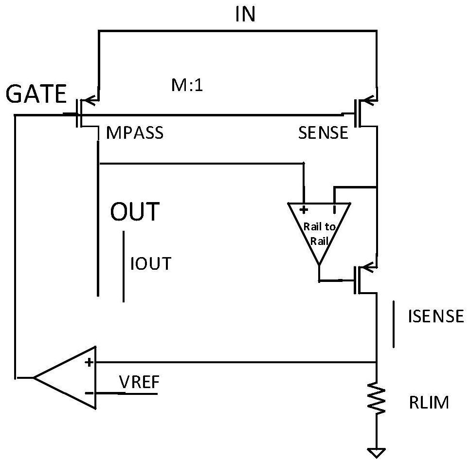
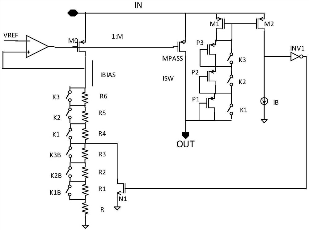
[0033] A P-type power transistor (positive channel metal oxide semiconductor, PMOS) is usually connected to the power port. When the power transistor is turned on, it can supply power to the load. When the power transistor is turned off, it does not supply power to the load. For example, figure 1 shown.

[0034] In the normal state wh...


PUM


Abstract

The invention provides a protection circuit of a power tube, the circuit comprises a bias branch connected to a grid electrode of the power tube and a clamping branch connected between a source electrode and a drain electrode of the power tube, the source electrode of the power tube is connected with an input end, the drain electrode of the power tube is connected with an output end, the bias branch is used for providing bias current, and the clamping branch is used for clamping the bias current. The output current of the power tube is limited by the bias current, and the clamping branch is used for reducing the bias current when the source-drain voltage of the power tube is greater than a source-drain clamping voltage threshold, so that the output current of the power tube is reduced, and the power tube enters a current-limiting protection mode to control the power. Thus, current limiting and clamping can be combined, the power of the power tube is limited, and the safety of the power tube is protected fundamentally.

Description

technical field [0001] The present application relates to the field of circuit technology, in particular to a power tube protection circuit, a power supply protection chip and electronic equipment. Background technique [0002] In the power protection chip, many will integrate the power switch tube. Wherein, the power switch tube is also referred to as a power tube, and the power tube is a transistor serving as a final stage output in an amplifying circuit. The power transistor may generally be a metal oxide semiconductor field effect transistor (MOSFET), also called a MOS. [0003] Power tubes can be divided into N-type power tubes and P-type power tubes. The P-type power tube is usually connected to the power port. When the power tube is turned on, it can supply power to the load, and when the power tube is turned off, it does not supply power to the load. Under normal circumstances, the P-type power tube works in the linear region. At this time, the gate-source voltage...

Claims


Application Information

Patent Timeline
Patent Type & Authority Applications(China)
IPC IPC(8): H02M1/32H02H7/20
Inventor 姜艳
Owner SHANGHAI AWINIC MICROELECTRONIC TECH CO LTD
Why Eureka
Try Eureka