Straw crushing and feeding machine for agricultural livestock
A straw pulverizing and feeding machine technology, which is applied in the field of straw pulverization, can solve the problems of being difficult to meet the needs of use, difficult to discharge, and the straw pulverizing effect is not good, and achieves compact overall structure design, convenient and rapid discharge, and poor solution effect. Effect
- Summary
- Abstract
- Description
- Claims
- Application Information
AI Technical Summary
Problems solved by technology
Method used
Image
Examples
Embodiment 1
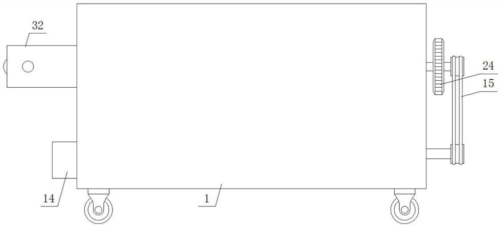
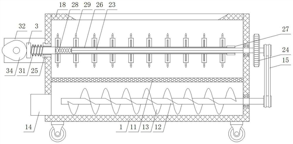
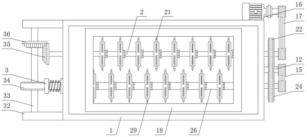
[0035] Embodiment 1: This embodiment provides a straw crushing feeder for agricultural livestock, see Figure 1-10 , specifically, including a bottom box 1, the bottom box 1 is a rectangular box with an open top surface, a top cover 18 is provided at the top surface opening of the bottom box 1, and a trapezoidal feed opening is provided in the middle of the top surface of the top cover 18 , the inner middle of the bottom box 1 is provided with a horizontally fixed arc-shaped sieve plate 11, an elliptical cavity is formed between the top surface of the arc-shaped sieve plate 11 and the inner top wall of the bottom box 1, and a transverse The horizontal shaft 2 connected by rotation; the top of the left side of the bottom box 1 is provided with a T-shaped ring 25 that penetrates and is fixed, and the inside of the T-shaped ring 25 is inserted with a sleeve 26 that slides through the horizontal direction, and the right end of the sleeve 26 extends to the right side in the ellipti...
Embodiment 2
[0044] Embodiment two: see figure 2 , in the first embodiment, there is also the problem of inconvenient discharge after straw crushing, therefore, on the basis of the first embodiment, this embodiment also includes:
[0045] In the present invention, the bottom of the left side of the bottom box 1 is provided with a fixed discharge channel steel 14, and the bottom of the right side of the bottom box 1 is provided with a third bearing hole, and the inside of the third bearing hole is provided with a concentric solid. The third bearing connected to the third bearing is inserted with a horizontally penetrating screw shaft 12 inside the third bearing. The left end of the screw shaft 12 extends to the inner port of the discharge channel steel 14, and is located on the screw shaft 12 in the bottom box 1. Several continuous helical and interlaced helical blades 13;
[0046] Located on the right side of the bottom box 1, the fourth sprocket wheel is set on the right end of the scre...
Embodiment 3
[0047] Embodiment three: see Figure 7-10 , in Embodiment 1, there is also the problem of inconvenient adjustment of the first grinding wheel and the second grinding wheel. Therefore, on the basis of Embodiment 1, the first grinding wheel 21 of this embodiment also includes a hollow disc 4 and several The arc-shaped blades arranged in a circle, the middle part of one side of the hollow disc 4 is concentrically sleeved on the horizontal shaft 2, a sliding gap is provided between the middle part of one side of the hollow disc 4 and the horizontal shaft 2, and the inside of the sliding gap is provided with Threaded cylinder 41, the outer wall of the threaded cylinder 41 is slidingly connected with the middle part of one side of the hollow disc 4, the inner wall of the threaded cylinder 41 is threadedly connected with the outer surface of the horizontal shaft 2, and the outer port of the threaded cylinder 41 is provided with a concentric fixed hexagon Nut ring 42; can drive thread...
PUM
 Abstract
Description
Claims
Application Information
 - R&D
- Intellectual Property
- Life Sciences
- Materials
- Tech Scout
- Unparalleled Data Quality
- Higher Quality Content
- 60% Fewer Hallucinations
Browse by: Latest US Patents, China's latest patents, Technical Efficacy Thesaurus, Application Domain, Technology Topic, Popular Technical Reports.
© 2025 PatSnap. All rights reserved.Legal|Privacy policy|Modern Slavery Act Transparency Statement|Sitemap|About US| Contact US: help@patsnap.com


