Supercharge Your Innovation With Domain-Expert AI Agents!

Self-calibration method of head moving CT detector and scanning system

A detector and self-calibration technology, which is applied in computerized tomography scanners, instruments for radiological diagnosis, medical science, etc., can solve the problems of uncertain use time, inability to have calibration, time constraints, etc., to achieve rapid self-calibration, The effect of quality assurance and accuracy assurance

Pending Publication Date: 2022-04-15
延安市中医医院
View PDF0 Cites 0 Cited by
  • Summary
  • Abstract
  • Description
  • Claims
  • Application Information

AI Technical Summary

Problems solved by technology

In the special application scenarios of head-moving CT (such as first aid or surgery), the use time is uncertain, and once it needs to be used, the time is very urgent. Basically, it is required that the head-moving CT can be turned on immediately. scan, there can be no calibration process
However, due to the particularity of its use, moving head CT cannot guarantee that the detector is always powered on and can work at any time. It is common that the system is not powered on until the system is to be used; while detector calibration is It can only be carried out after the system is powered on, so it brings more trouble and inconvenience to the application of mobile head CT

Method used


Image

  • Self-calibration method of head moving CT detector and scanning system
  • Self-calibration method of head moving CT detector and scanning system

Examples


Embodiment 1

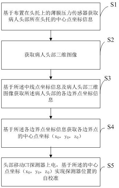
[0024] Such as figure 1 As shown, a self-calibration method of a head-moving CT detector in an embodiment of the present invention includes the following steps:

[0025] S1. Obtain the coordinate information of the center point of the headrest where the patient's head is located based on the thin-film pressure sensor arranged on the headrest; specifically, first obtain the contact area between the patient's head and the thin-film pressure sensor, and then obtain the patient by identifying the shape of the contact area. Coordinate information of the center point of the headrest where the head is located;

[0026] S2. Obtain a three-dimensional image of the patient's head; specifically, after the center point coordinate information collection of the head support is completed, the patient's head image is obtained through the camera, and then the depth image of the head image is obtained through the kinect depth sensor, and the obtained The depth image is triangulated, all triang...

Embodiment 2

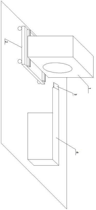
[0032] Such as figure 2 As shown, a self-calibration scanning system of a head-moving CT detector is used to realize the self-calibration method of the head-moving CT detector described in Embodiment 1, including a head-moving CT detector machine 1, rack rails 2. Head support 3, hospital bed 4 and camera; the head moving CT detector machine 1 is installed on the frame guide rail 2 of the movable base, the patient lies on the hospital bed 4, and the head is placed on the head support 3, and the head The upper surface of the support 3 is evenly covered with a thin-film pressure sensor, and a button for the user to wake up and sleep the thin-film pressure sensor is arranged on the side of the head support. It needs to be adjusted to the target position to collect the head image of the patient after lying flat. It also includes a data post-processing system, which is used to obtain the coordinate information of the center point of the headrest where the patient's head is located...


PUM


Abstract

The invention relates to the field of head movement CT detection, in particular to a self-calibration method of a head movement CT detector and a scanning system.The self-calibration method comprises the following steps that S1, coordinate information of the center point of a head support where the head of a patient is located is obtained based on a film pressure sensor arranged on the head support; s2, acquiring a three-dimensional image of the head of the patient; s3, acquiring coordinate information of each boundary point of the head of the patient based on the coordinate information of the midline point and the three-dimensional image of the head of the patient; s4, acquiring central point coordinates (x0, y0, z0) of each boundary point based on the coordinate information of each boundary point; and S5, electrifying the head moving CT detector, and realizing self-calibration of the position of the detector based on the central point coordinates (x0, y0, z0). According to the invention, rapid self-calibration of the head-moving CT detector can be realized, the accuracy of a self-calibration result can be ensured, and a guarantee is provided for the quality of an obtained CT scanning image.

Description

technical field [0001] The invention relates to the field of head moving CT detection, in particular to a self-calibration method and a scanning system of a head moving CT detector. Background technique [0002] CT (Computed Tomography) is an important clinical imaging diagnostic method. The moving head CT system is a special CT scanning system developed on the basis of traditional CT. Its free-moving head CT--CereTom can realize bedside and intraoperative head CT imaging without transferring patients. While improving the efficiency of medical work, it reduces the potential risk of patients due to transfer. In the special application scenarios of head-moving CT (such as first aid or surgery), the use time is uncertain, and once it needs to be used, the time is very urgent. Basically, it is required that the head-moving CT can be turned on immediately. Scan, there can be no calibration process. However, due to the special way of use of moving head CT, it is impossible to g...

Claims


Application Information

Patent Timeline
IPC IPC(8): A61B6/00A61B6/03
Inventor 王保奇张利杨洋魏田华蒋涛安雅宝
Owner 延安市中医医院
Features
  • R&D
  • Intellectual Property
  • Life Sciences
  • Materials
  • Tech Scout
  • Unparalleled Data Quality
  • Higher Quality Content
  • 60% Fewer Hallucinations
Learn More