Supercharge Your Innovation With Domain-Expert AI Agents!

Detection device for laser rangefinder

A technology of laser rangefinder and detection device, which is applied to radio wave measurement systems and instruments, etc., which can solve the problems of affecting the calibration accuracy, the inability to directly correlate the emitted laser energy with the received laser energy, and the target surface being easily damaged.

Inactive Publication Date: 2014-01-01
南瑶
View PDF5 Cites 0 Cited by
  • Summary
  • Abstract
  • Description
  • Claims
  • Application Information

AI Technical Summary

Problems solved by technology

The photoelectric simulation method mainly uses fast photodetectors, delay circuits, analog light sources and standard attenuators. The emitted laser energy of the laser rangefinder is not directly related to the received laser energy, and the optical axis of the simulated light source and the receiving system of the laser rangefinder is aligned. Quasi-debugging is difficult
The optical fiber simulation method usually uses a certain length of optical fiber to make a standard distance simulator, samples and delays the laser pulse, and inputs the laser pulse output from the optical fiber into the receiving system of the laser rangefinder for a single distance simulation, and one optical fiber can only simulate One distance; the calibration methods of the simulated distance and laser energy attenuation loss of the standard distance simulator include the truncation method, the insertion method, the backscattering method and the comparison method, which have the disadvantages of large measurement uncertainty and damage to the optical fiber
The calibration of the laser emitting optical axis and the aiming optical axis of the laser rangefinder usually adopts the focusing method of a large-diameter parabolic mirror. There are deficiencies that the target surface at the focal plane is easy to be damaged and invisible, which affects the calibration accuracy. The laser receiving optical axis usually adopts a structural guarantee.
There is no relevant report on the direct and comprehensive detection of the laser energy emitted by the laser range finder, the distance, the minimum detectable laser power of the receiving system, and the coaxiality of the optical axis.

Method used


Image

  • Detection device for laser rangefinder
  • Detection device for laser rangefinder
  • Detection device for laser rangefinder

Examples


Embodiment 1

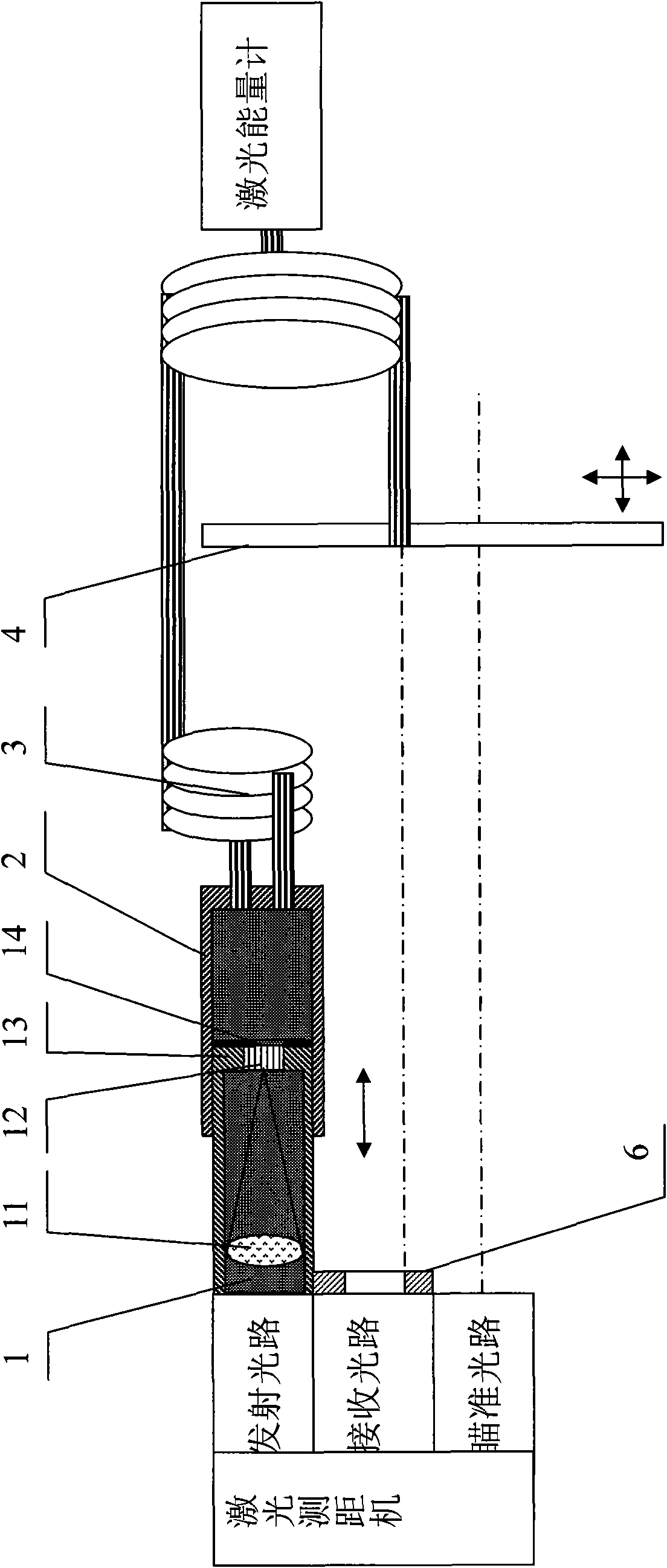
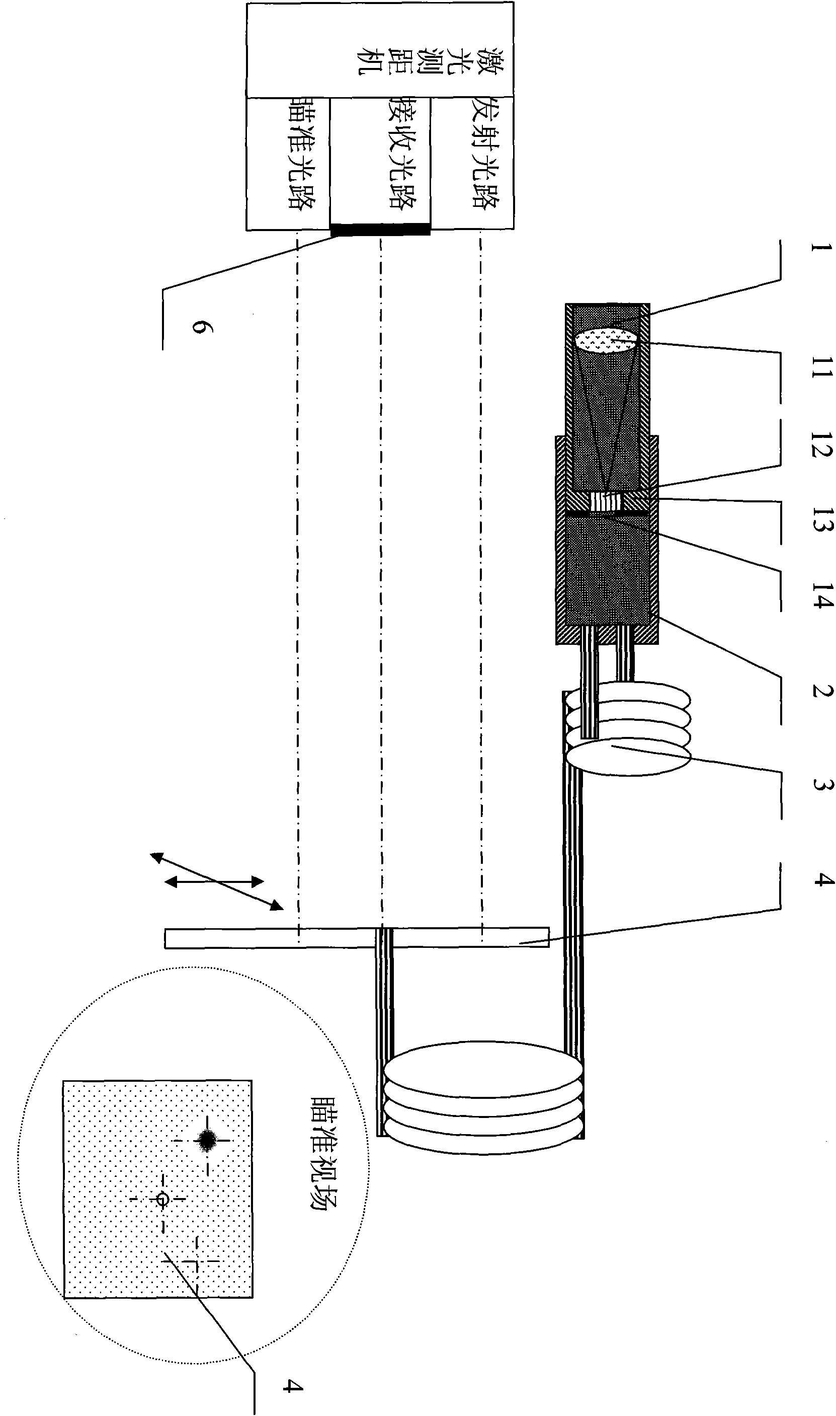
[0035] according to figure 1 , The preferred embodiment 1 of the present invention detects a laser rangefinder with a laser wavelength of 1.064 μm, including a sampler 1, an absorber 2, a multi-target simulator 3, a standard target plate 4, and an iris 6. The sampler 1 includes a standard lens 11, a beam expander 12, a mirror tube 13, and a small target aperture 14. The standard lens 11 is preferably an aberration lens made of quartz with a focal length of 300mm and a diameter of 30mm. The effective light diameter of the launching optical path is 30mm; the beam expander 12 is preferably made of a quartz fiber, a bare fiber rod with a length of 5mm, which is cut by a special tool, and the outer diameter of the fiber rod is coated with a metal reflective film to form a compact beam; preferably small The target aperture 14 has a through hole 0.4mm in the middle, the laser spot at the focal plane position of the standard lens is 0.6mm, and the ratio of the target cross-section to th...

Embodiment 2

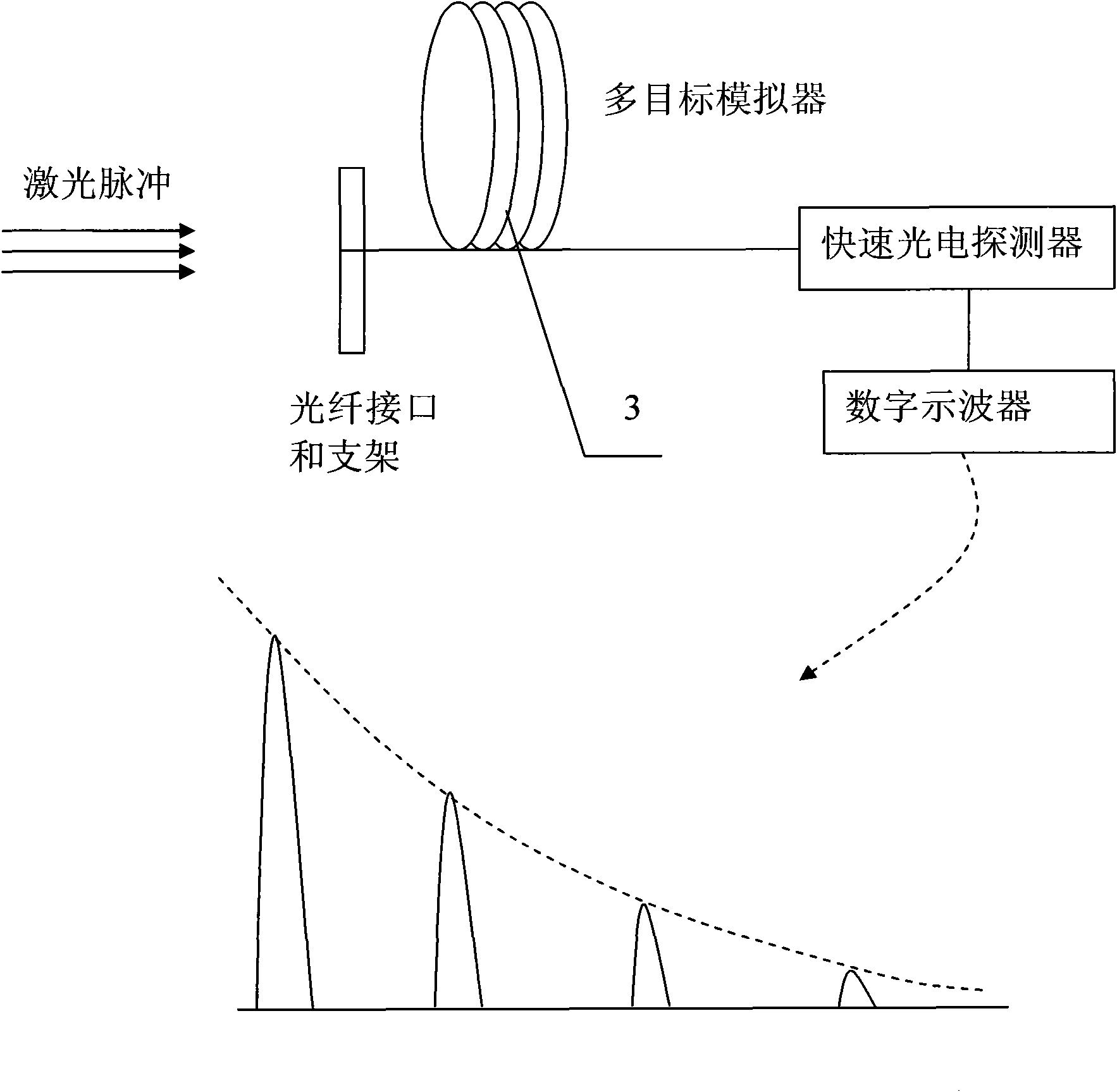
[0040] according to figure 1 The preferred embodiment 2 detects a laser rangefinder with a laser wavelength of 10.6 μm, including a sampler 1, an absorber 2, a multi-target simulator 3, a standard target plate 4, and an iris diaphragm 6. Preferably, the standard lens 11 of the sampler 1 is a germanium lens that transmits far-infrared light, and the beam expander 12 is preferably made of As-Se fiber material and a bare fiber rod with a length of 5 mm, which is cut by a special tool. Metallized reflective film, compactly bundled; preferably, the small target aperture 14 is made of ceramic material; preferably, the multi-target simulator 3 is composed of 2x5 As-S fibers with different lengths, and the lengths are 51m, 53m, 57m, 59m, Two 61m each. Preferably, the input / output end face of the As-S fiber is flat and perpendicular to the optical axis of the fiber, coated with a reflective film with the same wavelength of 10.6μm for the laser; the simulation distance of the multi-target...

Embodiment 3

[0042] according to Figure 4 , The preferred embodiment 3 performs long-distance detection on the laser rangefinder, including the multi-target simulator 3, the standard target board 4, the self-focusing lens 5 and the interface. The distance between the laser rangefinder and the standard target board 4 is 60m, and the standard target The surface of the board 4 is perpendicular to the laser optical axis, and the self-focusing lens optical axis is coaxial with the laser optical axis, emitting laser distance measurement, adjusting the strobe distance of the laser distance measuring machine, and evaluating the performance of the laser distance measuring machine according to the distance measuring result.


PUM


Abstract

The invention discloses a detection device for a laser rangefinder, composed of a sampler, an absorber, a multi-target simulator, a standard target and a variable diaphragm. The laser rangefinder emits a laser directed at the detection device; the sampler and the multi-target simulator simulate a laser target echo, and obtain an receiving optical axis and the minimum detectable power of the laser rangefinder via the maximum distance ranging result; a laser emitting optical axis and a collimation optical axis are corrected via a laser spot position and an axis distance; and the emission and the receiving of the laser rangefinder are quantitatively associated, in order to realize a ranging capacity evaluation of the laser rangefinder. The device disclosed by the invention has no need to be supplied with power, and is simple in operation and low in cost.

Description

Technical field [0001] The detection field of the laser rangefinder of the present invention mainly relates to a measuring device for detecting and calibrating the laser rangefinder at the use site of the laser rangefinder, and particularly relates to a laser rangefinder detecting and calibrating the laser rangefinder on site that is not restricted by the environment and site. Calibrated measuring method and measuring device. Background technique [0002] Whether the performance and technical indicators of the laser rangefinder are normal is the user's most concern. The maximum range, minimum range, range accuracy, and extinction ratio of the laser rangefinder to different targets under certain environmental conditions are the main technical indicators for the evaluation of range finding capabilities. Other technical indicators that affect the performance of the laser rangefinder include the beam divergence of the emitted laser, laser spot mode, laser optical axis jitter, laser ...

Claims


Application Information

Patent Timeline
Patent Type & Authority Patents(China)
IPC IPC(8): G01S7/497
Inventor 不公告发明人
Owner 南瑶
Features
  • R&D
  • Intellectual Property
  • Life Sciences
  • Materials
  • Tech Scout
  • Unparalleled Data Quality
  • Higher Quality Content
  • 60% Fewer Hallucinations
Learn More