Universal rolling mill with structure for preventing pull rod of guide and guard beam from warping in roll changing process

A universal rolling mill and guide beam technology, applied in the direction of metal rolling stand, metal rolling mill stand, metal rolling, etc., can solve the problems of tedious installation and debugging of roll system, time-consuming and laborious, low efficiency, etc. The tilting head of the Weiliang tie rod improves the effect of maintenance and convenient operation

Pending Publication Date: 2022-04-15
中重科技(天津)股份有限公司
View PDF0 Cites 0 Cited by
  • Summary
  • Abstract
  • Description
  • Claims
  • Application Information

AI Technical Summary

Problems solved by technology

The guide beam tie rod of the existing universal rolling mill locks the drive side and the operation side bracket through the washer nut, and the nut is removed when changing the roll, and the drive side and the operation side bracket are separated by the roll change manipulator, so that the guide beam pull rod is pulled out, Then replace the rolls, but since the installation requires a large gap between the guide beam pull rod and the upper holes of the brackets on the operation side and the transmission side, after the roll change is completed, install the guide beam pull rod and the operation side bracket first. The tie rods of the guard beams will tilt their heads, which will make it very inconvenient to install the drive side brackets. In addition, there are four pieces of the same tie rods for each universal rolling mill. This problem makes the installation and debugging of the roll system extremely cumbersome and inefficient. , time-consuming and labor-intensive, so it is necessary to improve the structure of the universal rolling mill roll change to prevent the head of the guide beam tie rod from warping

Method used


Image

  • Universal rolling mill with structure for preventing pull rod of guide and guard beam from warping in roll changing process
  • Universal rolling mill with structure for preventing pull rod of guide and guard beam from warping in roll changing process
  • Universal rolling mill with structure for preventing pull rod of guide and guard beam from warping in roll changing process

Examples


Embodiment 1

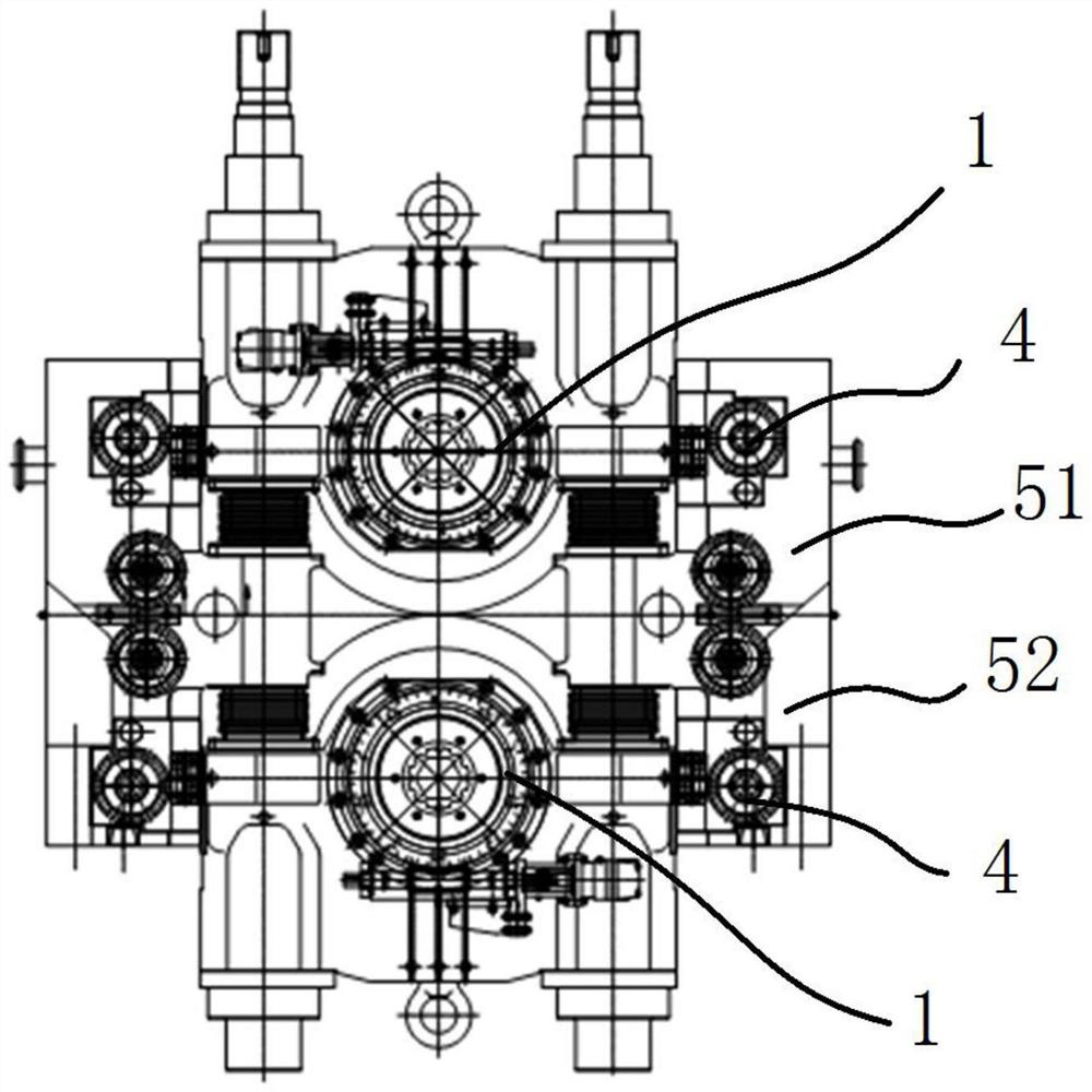
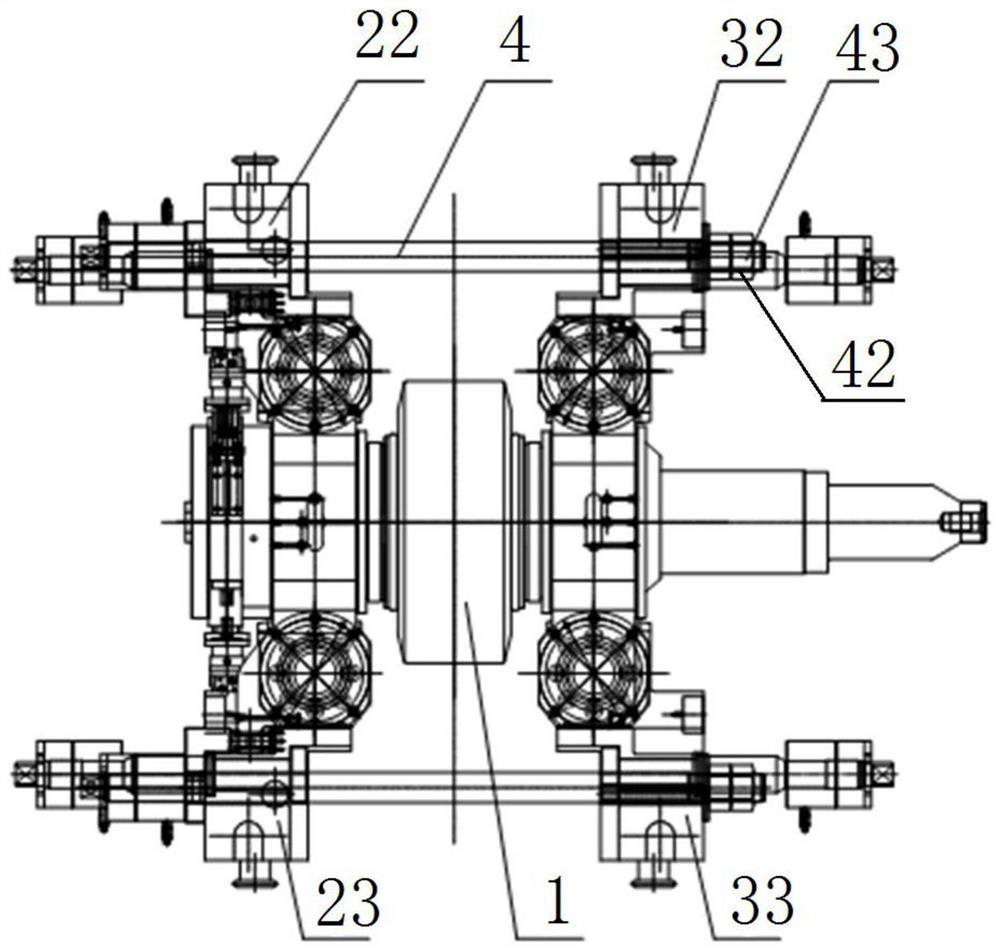
[0045] Embodiment 1: One end of the guide beam 4 has a threaded part 42 at one end, and the other end has a limiting part 41 (similar to a large bolt structure), and the outer diameter of the limiting part 41 is greater than the outer diameter of the pull rod in the middle of the guide beam 4 , while the outer diameter of the limiting portion 41 is greater than the inner diameter of the first through hole 21, to ensure that the guide beam 4 passes through the first through hole 21, the limiting portion 41 can fit the first through hole 21 The outer wall realizes the function of limiting, and then the middle part of the guide beam 4 passes through the fourth conduction hole of the guide device 5 in turn, and then passes through the second conduction hole 31 on the transmission side, and then passes through the second conduction hole 31 on the second guide beam. The through hole 31 is away from the opening on the side of the first through hole 21, and the guide beam 4 is tightene...

Embodiment 2

[0046] Embodiment 2: Both ends of the guide beam 4 are threaded parts 42, and the connection method of the threaded part 42 on the transmission side is the same as that of Embodiment 1, the difference is that the limiting part 41 in the original embodiment 1 is provided with hydraulic pressure Lock nut 8, hydraulic lock nut 8 adopts prior art and gets final product, by connecting the threaded portion 42 at one end of guide beam 4 with the inner thread in the inner cavity 83 of hydraulic lock nut 8, realize the fixing of the two, Simultaneously, the internal thread of inner cavity 83 is on the first piston rod 82 of hydraulic locking nut 8, as Figure 8As shown, the specific implementation process is as follows. First, the first piston rod 82 is driven to move to the right, and then the threaded part 42 at the right end of the guide beam 4 is screwed onto the nut 43. The side bracket 3 is fixed, but it is not strong enough. At this time, the first piston rod 82 is driven to mov...


PUM


Abstract

The invention provides a universal rolling mill with a structure for preventing a pull rod of a guide and guard beam from warping in a roll changing process, which comprises an operation side bracket and a transmission side bracket which are arranged on two sides of a roll, and further comprises the guide and guard beam, the guide and guard beam is used for fixing a guide and guard device, and the guide and guard device is used for correcting the position of a rolled piece; the two ends of the guide beam are erected on the operation side support and the transmission side support respectively. The operation side support and the transmission side support are provided with a first through hole and a second through hole respectively. The two ends of the guide and guard beam penetrate through the first through hole and the second through hole. A counter bore used for containing the supporting assembly is formed in the opening portion, close to one end of the second via hole, of the first via hole, and the supporting assembly is embedded into the counter bore. The universal rolling mill with the structure for preventing the pull rod of the guide and guard beam from tilting in the roll changing process has the beneficial effects that the copper sleeves are additionally arranged at the guide and guard beam mounting positions of the left bracket and the right bracket on the operation side and are used for supporting and positioning the guide and guard beam, so that the phenomenon of tilting of the guide and guard beam is prevented.

Description

technical field [0001] The invention belongs to the field of rolling mills, and in particular relates to a universal rolling mill with a structure for preventing guide and guard beam tie rods from warping during roll changing. Background technique [0002] The universal rolling mill is an important piece of equipment on the steel rolling production line, and changing the rolls of the rolling mill rolls is a common operation. The guide beam tie rod of the existing universal rolling mill locks the drive side and the operation side bracket through the washer nut, and the nut is removed when changing the roll, and the drive side and the operation side bracket are separated by the roll change manipulator, so that the guide beam pull rod is pulled out, Then replace the rolls, but since the installation requires a large gap between the guide beam pull rod and the upper holes of the brackets on the operation side and the transmission side, after the roll change is completed, install...

Claims


Application Information

Patent Timeline
Patent Type & Authority Applications(China)
IPC IPC(8): B21B31/08B21B39/16
Inventor 邢毅魏迪明
Owner 中重科技(天津)股份有限公司
Why Eureka
Try Eureka