Slicing device for soap processing and production
A soap cutting technology, applied in metal processing, non-rotational vibration suppression, etc., can solve the problems of inconvenient collection, not much soap, and inability to cut soap, so as to achieve rapid collection and treatment, avoid pollution, and avoid soap damage Effect
- Summary
- Abstract
- Description
- Claims
- Application Information
AI Technical Summary
Problems solved by technology
Method used
Image
Examples
Embodiment approach 1
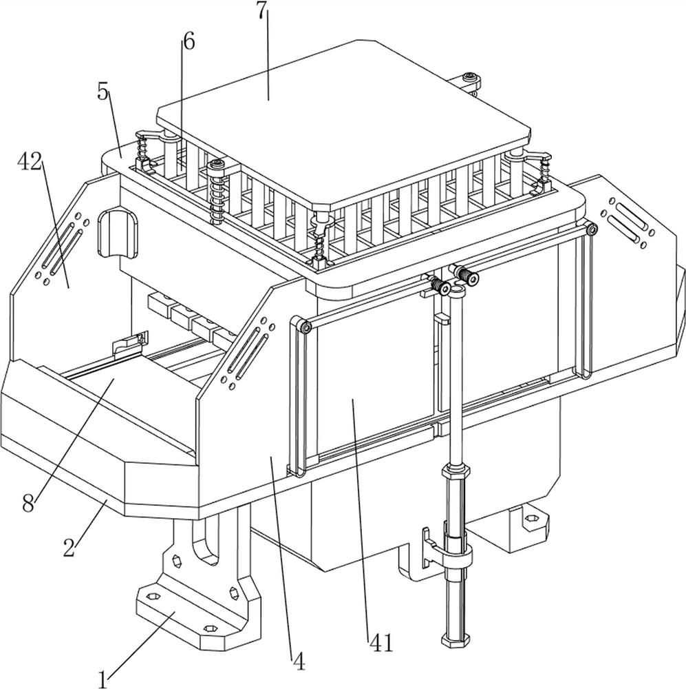
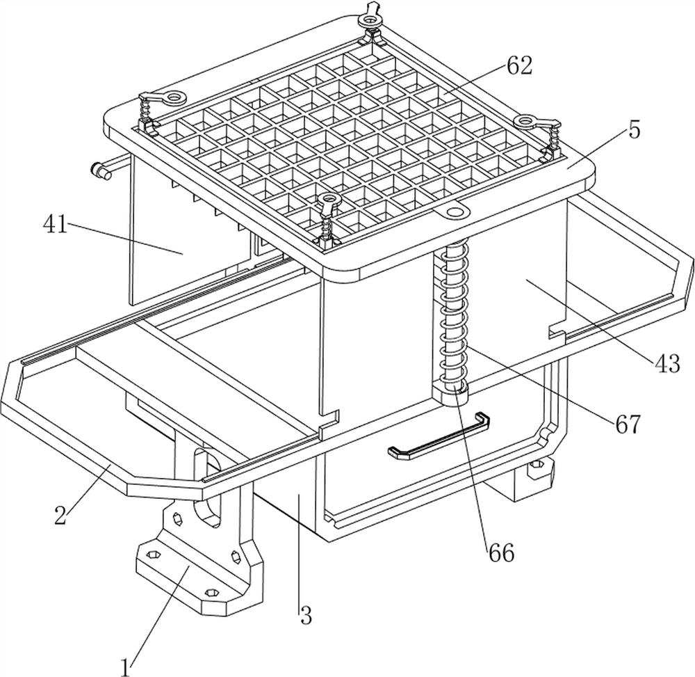
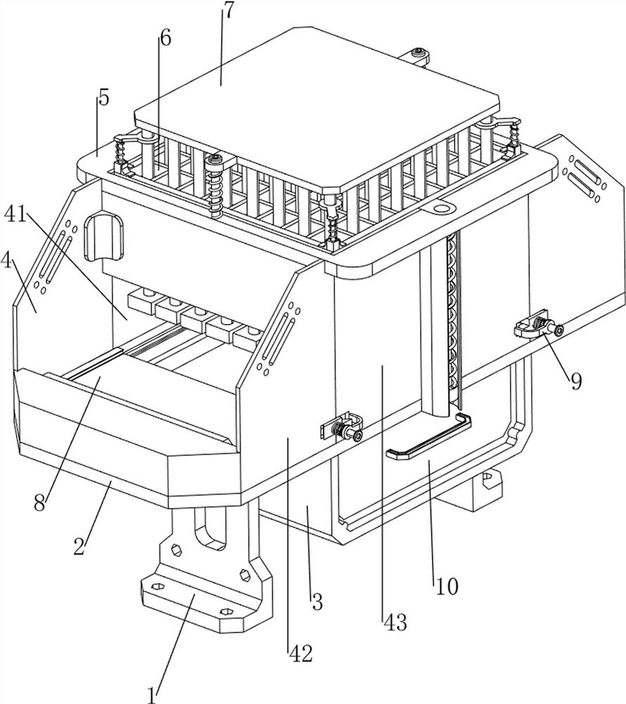
[0036] A cutting device for soap processing and production, as attached figure 1 , attached figure 2 , attached image 3 , attached Figure 4 , attached Figure 5 , attached Figure 9 And attached Figure 10 As shown, it includes a support leg 1, a fixed frame 2, a box body 3, a protective mechanism, a first installation frame 5, a cutting mechanism 6 and a feeding mechanism 8, and the left and right sides of the bottom of the fixed frame 2 are connected with a support leg 1 by bolts. The material of the supporting leg 1 is aluminum alloy, which is light in weight and relatively hard in strength. The box body 3 is bolted to the middle part of the lower side of the fixed frame 2. The fixed frame 2 is provided with a protective mechanism, and the protective mechanism is provided with a first installation frame 5. A cutting mechanism 6 is arranged on the first installation frame 5 , and a feeding mechanism 8 is arranged on the fixed frame 2 .
[0037] as attached figure 1...
Embodiment approach 2
[0042] On the basis of implementing method 1, as attached figure 1 , attached Figure 7 , attached Figure 8 And attached Figure 9 As shown, the auxiliary mechanism 7 is also included, and the auxiliary mechanism 7 includes a fixed plate 71, a connecting rod 72, a pressing block 73, a second guide rod 74, a second return spring 75, a first pressing plate 76, a mounting rod 77, a second Pressing plate 78 and the first connection spring 79, the left and right symmetrical formula on the first installation frame 5 upper side is provided with the second guide rod 74, slide type is provided with fixed plate 71 between two second guide rod 74 tops, fixed plate 71 and the first A second back-moving spring 75 is connected between the mounting frame 5, and the four corners on the upper side of the second mounting frame 61 are all slidably provided with mounting rods 77, and the top of the mounting rods 77 is connected with a second pressing plate 78. The first connection spring 79 i...
Embodiment approach 3
[0045] On the basis of implementing method 2, as attached figure 1 , attached Figure 5 And attached Image 6 As shown, it also includes a discharge mechanism 9, and the discharge mechanism 9 includes a fixed block 91, a third return spring 92, a connecting plate 93, a third guide rod 94, a fourth return spring 95, a first wedge block 96 and a first wedge block 96. Two wedge-shaped blocks 97, the two inner walls of the fixed frame 2 left and right are connected with a fixed block 91, the third back-moving spring 92 is connected between the fixed block 91 and the second push plate 88 on the same side, and the fourth mounting plates 43 of the two pieces are separated. One side is all welded and connected with connecting plate 93, and the third guide rod 94 is run through in sliding type on the connecting plate 93, and the third guide rod 94 rear portion is bolted with first wedge-shaped block 96, and the second push plate 88 can be connected with the first The wedge blocks 96 ...
PUM
 Abstract
Description
Claims
Application Information
 - R&D
- Intellectual Property
- Life Sciences
- Materials
- Tech Scout
- Unparalleled Data Quality
- Higher Quality Content
- 60% Fewer Hallucinations
Browse by: Latest US Patents, China's latest patents, Technical Efficacy Thesaurus, Application Domain, Technology Topic, Popular Technical Reports.
© 2025 PatSnap. All rights reserved.Legal|Privacy policy|Modern Slavery Act Transparency Statement|Sitemap|About US| Contact US: help@patsnap.com


