Tow conveying device for composite material tow laying equipment

A technology for conveying devices and composite materials, which is applied in the directions of transportation and packaging, delivery of filamentous materials, and thin material processing, etc. It can solve problems such as the decline in the quality of the tow, poor use of the tow, and impact, and achieve the goal of reducing friction Effect

Pending Publication Date: 2022-04-15
AVIC BEIJING AERONAUTICAL MFG TECH RES INST
0 Cites 0 Cited by

AI-Extracted Technical Summary

Problems solved by technology

Although the factory environment is required to ensure constant temperature, constant humidity and dust-free during the process of laying the tow, due to the influence of other uncertain environmental factors such as personnel flow, the quality of the tow will often decrease during the transmission process
[0004] Compared with the equipment in which the creel and the laying head are separated, the tow laying equipment nee...

Method used

For convenience of understanding, tow tube 4, the leaf spring 2 that is pressed on both sides of tow tube 4, and the sheath 3 that is enclosed within tow tube 4 and spring leaf 2 are taken as an integral pipeline, are defined as Delivery pipeline. When the silk laying head rotates during the laying process, it will move relative to the creel, ca...

Abstract

The invention belongs to the technical field of tow laying equipment, and particularly relates to a tow conveying device for composite material tow laying equipment. The tow conveying device comprises a tow inlet assembly, a conveying pipeline and a tow outlet assembly. The conveying pipeline comprises a spring piece, a sheath and a tow tube; the tow inlet assembly and the tow outlet assembly are connected through a tow pipe. The two spring pieces are symmetrically arranged on the two sides of the tow tube. According to the tow conveying device, the low-resistance pipeline is utilized, and friction loss between tows and the pipeline in the tow conveying process is reduced; the conveying channel of the tows is provided with a fixing and protecting device of a corresponding pipeline, so that the tows can be smoothly conveyed when the conveying channel is twisted and bent, and meanwhile, the tow pipe can be prevented from being damaged when the tow pipe is twisted, bent and the like.

Application Domain

Filament handling

Technology Topic

Friction lossComposite material +2

Image

  • Tow conveying device for composite material tow laying equipment
  • Tow conveying device for composite material tow laying equipment
  • Tow conveying device for composite material tow laying equipment

Examples

  • Experimental program(1)

Example Embodiment

[0032] In order to make the purposes, technical solutions and advantages of the embodiments of the present invention clearer, the technical solutions in the embodiments of the present invention will be clearly and completely described below with reference to the accompanying drawings in the embodiments of the present invention. Obviously, the described embodiments These are some embodiments of the present invention, but not all embodiments. Based on the embodiments of the present invention, all other embodiments obtained by those of ordinary skill in the art without creative efforts shall fall within the protection scope of the present invention.
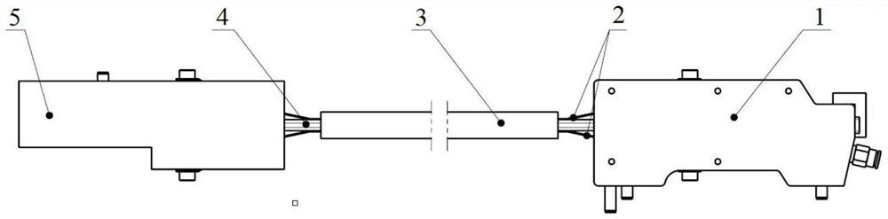
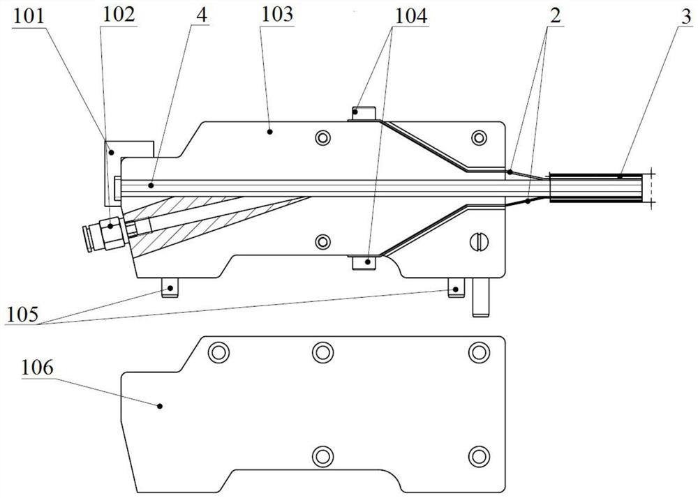
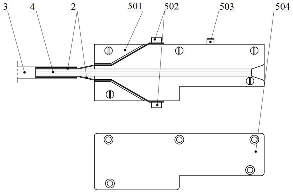
[0033] The embodiment of the present invention provides a tow conveying device for composite tow laying equipment, such as Figure 1-5 As shown, the tow conveying device includes a tow inlet assembly 1 , a spring leaf 2 , a sheath 3 , a tow tube 4 and a tow outlet assembly 5 . The tow inlet assembly 1 and the tow outlet assembly 5 are connected by the tow tube 4; the two spring pieces 2 are symmetrically arranged on both sides of the tow tube 4, and the two ends of the spring piece 2 are respectively connected to the tow. The inlet assembly 1 and the tow outlet assembly 5 are fixedly connected, and the two spring pieces 2 both exert a pressing force on the tow tube 4, which is used to prevent the tow tube 4 from bending, twisting, etc. when bending or twisting. damage. The sheath 3 is sleeved on the outside of the tow tube 4 and the spring sheet 2, and the sheath 3 is in the form of a corrugated tube, which is used to prevent the spring sheet 2 pressed on both sides of the tow tube 4 from being in the tow tube 4. When bending and twisting are performed, movement occurs and cannot be attached to the outer wall of the tow tube 4 .
[0034] Specifically, as figure 2 As shown, the tow inlet assembly 1 includes a wire feed fixing plate 101, a quick-plug connector 102, a first mounting seat 103, a first fixing screw 104, a first positioning pin 105 and a first cover plate 106; the wire feed The fixing plate 101 is fixedly installed at one end of the first mounting seat 103 , and the wire feeding fixing plate 101 is used to fix the tow tube 4 to prevent it from sliding in the first mounting seat 103 ; one side of the first mounting seat 103 On the board surface, a set of first tow tube installation grooves, two sets of first spring sheet grooves and a set of air passages are arranged, one end of the air passage is communicated with the first tow tube installation groove, and the other side of the air passage is connected. One end runs through the first mounting seat 103, and two sets of first spring sheet grooves are symmetrically arranged on both sides of the first tow tube installation groove; a section of the tow tube 4 is embedded in the first tow tube installation groove , and the tow tube 4 passes through the first mounting seat 103 and is located on one side of the wire feed fixing plate 101; the two spring pieces 2 are located on both sides of the tow tube 4, and a section of the two spring pieces 2 are respectively Nested in the two sets of first spring sheet grooves, and one end of the two spring sheets 2 penetrates the first mounting seat 103 and is fixedly mounted on the first mounting seat 103 by the first fixing screw 104; The quick-plug connector 102 is installed in one end of the air passage close to the outer wall of the first mounting seat 103 . The first cover plate 106 is mounted on one side surface of the first mounting seat 103 by bolts, and is used to limit the tow tube 4 , the spring sheet 2 and the quick-connect joint 102 mounted on the first mounting seat 103 . position and protection. The first positioning pin 105 is installed on the first mounting seat 103 , and the tow inlet assembly 1 can be installed on the creel through the first positioning pin 105 .
[0035]The tow outlet assembly 5 includes a second mounting seat 501, a second fixing screw 502, a second positioning pin 503 and a second cover plate 504; a set of second The tow tube installation groove and two sets of second spring leaf grooves, the two sets of second spring leaf grooves are symmetrically arranged on both sides of the second tow tube installation groove; a section of the tow tube 4 is embedded in the second tow one end of the tow tube 4 penetrates the second mounting seat 501; a section of the two spring sheets 2 is respectively embedded in the two sets of second spring sheet grooves, and the two spring sheets One end of 2 penetrates through the second mounting seat 501 , and is fixedly mounted on the second mounting seat 501 by a second fixing screw 502 . The second cover plate 504 is mounted on one side surface of the second mounting seat 501 by bolts, and is used to limit and protect the tow tube 4 and the spring sheet 2 mounted on the second mounting seat 501 . The second positioning pin 503 is mounted on the second mounting seat 501 , and the tow outlet assembly 5 can be mounted on the laying head through the second positioning pin 503 .
[0036] further, as Figure 4 As shown, the cross section of the tow tube 4 is rectangular as a whole, and the cross section of the passage in the tow tube 4 is also rectangular, and the size of the cross section of the passage in the tube can be adjusted according to the size of the tow 6 . It should be noted that the cross-sectional size of the channel in the tube is larger than the cross-sectional size of the tow 6 . The tow tube 4 is made of elastic material, which can be bent and twisted to a certain extent. For example, the material of the tow tube 4 is high-density ethylene HDPE or ultra-high molecular polyethylene UPE, and an antistatic agent is added to the material, and the friction coefficient between the used material and the material of the tow 6 is small. The tube inner wall of the tow tube 4 has a low roughness, and is provided with several groups of arc protrusions 402 to prevent the tube inner wall from being too smooth and flat, and attracting force with the surface of the tow 6, resulting in increased wire feeding tension.
[0037] One end of the tow tube 4 has a flash, which is used for installation with the first mounting seat 103. The size of the flash is larger than the cross-sectional size of the first tow installation groove, so that a section of the tow tube 4 is embedded in the first tow. When the tow is installed in the groove, the flash edge is closely attached to the outer wall of the first installation seat 103 .
[0038] The tow tube 4 is provided with an air inlet 401 at a position close to the flash. In the tow inlet assembly 1 , the air inlet 401 is located at the connection between the air passage and the first tow installation groove, and one end of the air passage communicates with the air inlet 401 . A certain pressure of cooling gas is input into the air passage through the push-in connector 102 , and the cooling gas can enter the tow tube 4 through the air inlet 401 .
[0039] The tow 6 enters the tow tube 4 through the end provided with the flash edge, and is transported from the tow inlet assembly 1 to the tow outlet assembly 5 through the tow tube 4 by the pulling action of the laying head. Since the cross-section of the channel in the tow tube 4 is rectangular, and the cross-sectional size of the channel in the tow tube 4 is larger than that of the tow 6, when the tow tube 4 is twisted, it will not cause the inside of the tow tube 4 to be twisted. The tow 6 is twisted.
[0040] In addition, in the process of conveying the tow, the pipeline outputting a certain pressure of cooling gas is inserted into the quick-connect joint 102, and the cooling gas in the cooling pipeline enters the inside of the tow tube 4 through the air passage and the air inlet 401. Provide a certain pressure of cooling gas for the tow in the tow tube 4 to keep the tow at a constant temperature during transportation, prevent the tow from performance degradation due to temperature changes, and at the same time play the role of dust and pollution prevention. At the same time, a certain pressure of cooling gas is introduced to accelerate the gas flow in the tow tube 4, and the cooling gas is applied from the surface of the tow 6 in contact with the tow tube 4 to achieve a certain air flotation effect, such as Figure 5 As shown, the transport resistance of the tow 6 within the tow tube 4 is reduced. The arc protrusion 402 in the tow tube 4, compared with the structure of the smooth inner wall adopted in the prior art, is used to prevent the inner wall of the tube from being too smooth and flat, and to generate an adsorption force with the surface of the tow 6, resulting in an increase in the wire feeding tension .
[0041] For the convenience of understanding, the tow tube 4, the spring pieces 2 pressed on both sides of the tow tube 4, and the sheath 3 sheathed outside the tow tube 4 and the spring pieces 2 are regarded as a whole pipeline, which is defined as a conveying pipeline. . When the laying head rotates and other actions during the laying process, it moves relative to the creel, so that the tow tube 4 is bent and twisted. The spring pieces 2 on both sides of the tow tube 4 bear, reducing the force of the tow tube 4, preventing the tow tube 4 from being broken and twisted, resulting in the phenomenon that the tow 6 cannot be transported, and has a protective effect on the tow tube 4.
[0042] Exemplary as Image 6 As shown, in a 16 tow horizontal composite material tow laying equipment, the laying head 8 and the creel 7 are separate structures. The 16 tow inlet assemblies 1 are integrated together, installed on the creel 7 and positioned by the first positioning pins 105 to assemble the tow inlet device 9 . The 16 tow outlet assemblies 5 are integrated, installed on the laying head 8, positioned by the second positioning pins 503, and assembled into the tow outlet device 11. Each tow inlet assembly 1 and a corresponding tow outlet assembly 5 are connected by a conveying pipeline of a certain length. The 16 conveying pipelines pass through the thermal insulation protection pipe 10 , and the two ends of the thermal insulation protection pipe 10 are respectively fixed on the laying head 8 and the creel 7 . A certain pressure of cooling gas is introduced into the 16 tow tubes 4 in the thermal insulation protection tube 10 through the tow inlet assembly 1 to prevent the tow from sticking in the tow tubes 4 . It should be noted that, cooling gas can also be introduced into the thermal insulation protection pipe 10 to provide a cooling environment outside the conveying pipeline.
[0043] After passing through the tension reduction mechanism in the creel 7 , the 16 tow 6 respectively enter into the 16 tow tubes 4 , and finally enter into the laying head 8 . In the process of laying the tow, one end of the tow 6 is subjected to the rolling and laying action of the laying head 8 , and the tow 6 is drawn to be transported in the tow tube 4 . During this process, the push-in joints 102 in the 16 tow inlet assemblies 1 are all connected to the pipelines that provide cooling gas from the vortex cooling generator, so that a certain pressure and temperature are always introduced into each tow tube 4 cooling gas.
[0044] During the laying of the tow, the laying head 8 performs swinging and rotating motions. The tow tube 4 also rotates and twists under the driving of the heat preservation and protection tube 10 connected between the laying head 8 and the creel 7 . At this time, the tow 6 in the tow tube 4 is still transported smoothly under the combined action of the cooling gas in the tube, the spring sheet 2 outside the tube, and the sheath 3, and the tow 6 transported to the laying head 8 has good quality quality.
[0045] Although the present invention has been described in detail with reference to the foregoing embodiments, those of ordinary skill in the art should understand that: it is still possible to modify the technical solutions described in the foregoing embodiments, or perform equivalent replacements to some of the technical features; and these Modifications or substitutions do not make the essence of the corresponding technical solutions deviate from the spirit and scope of the technical solutions of the embodiments of the present invention.

PUM

no PUM

Description & Claims & Application Information

We can also present the details of the Description, Claims and Application information to help users get a comprehensive understanding of the technical details of the patent, such as background art, summary of invention, brief description of drawings, description of embodiments, and other original content. On the other hand, users can also determine the specific scope of protection of the technology through the list of claims; as well as understand the changes in the life cycle of the technology with the presentation of the patent timeline. Login to view more.

Similar technology patents

Oil film supporting servo hydraulic cylinder

Owner:WUHAN UNIV OF SCI & TECH

Masking plate and array substrate manufacturing method

InactiveCN107275522Areduce frictionreduce scratches
Owner:SHANGHAI TIANMA AM OLED

Novel air distribution system with variable lift

ActiveCN101446218Areduce frictionReduce pumping loss
Owner:CHERY AUTOMOBILE CO LTD

Classification and recommendation of technical efficacy words

  • reduce friction

Hand force feedback and sensing system

InactiveUS7138976B1reduce friction
Owner:RUTGERS UNIVERSITY

Electrical connector with voltage detection point insulation shield

ActiveUS6843685B1reduce frictionreduces wear and clean
Owner:THOMAS & BETTS INT INC

One piece low drag septum

ActiveUS20070093778A1reduce friction
Owner:BECTON DICKINSON & CO

Combination oil ring

InactiveUS20060113730A1reduce frictionenhanced capability
Owner:TOYOTA JIDOSHA KK +1
Why Eureka
Try Eureka