Gas distributor

A gas distributor, gas technology, applied in gas/liquid distribution and storage, utilization of plasma, machine/engine, etc., can solve problems such as unsolvable, achieve the effect of small size, good homogenization, and prolong homogenization time

Pending Publication Date: 2022-04-15
SHANGHAI INST OF SPACE PROPULSION
View PDF10 Cites 4 Cited by
  • Summary
  • Abstract
  • Description
  • Claims
  • Application Information

AI Technical Summary

Problems solved by technology

However, the flow of gas in the gas distributor in this scheme is still in the axial direction, which still cannot solve the above shortcomings

Method used


Image

  • Gas distributor
  • Gas distributor
  • Gas distributor

Examples


Embodiment Construction

[0034] The present invention will be described in detail below in conjunction with specific embodiments. The following examples will help those skilled in the art to further understand the present invention, but do not limit the present invention in any form. It should be noted that those skilled in the art can make several changes and improvements without departing from the concept of the present invention. These all belong to the protection scope of the present invention.

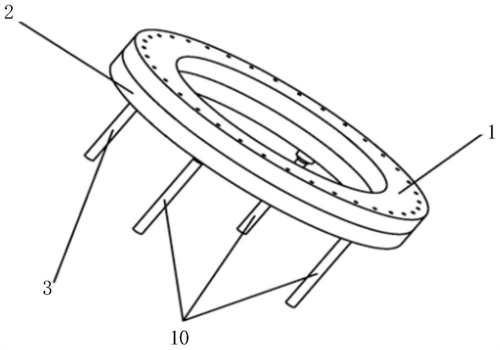
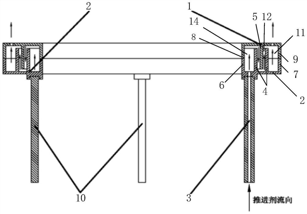
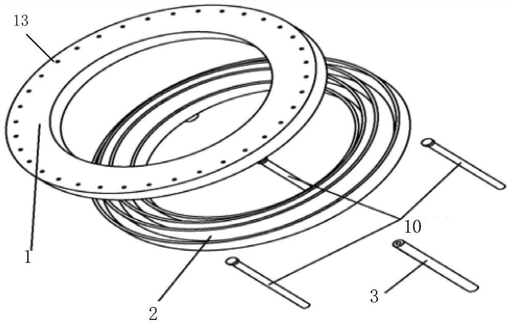
[0035] The invention provides a gas distributor, including a top structure, a bottom structure and an air pipe 3; as figure 1 and image 3 As shown, the bottom structure includes a bottom plate 2, a first partition 4, a first inner wall 6 and a first outer wall 7; An outer wall 7; the first partition 4, the first inner wall 6 and the first outer wall 7 all extend circumferentially along the top end of the bottom plate 2, and the first partition 4 is arranged on the first inner wall 6 and the first oute...


PUM


Abstract

The invention provides a gas distributor. The gas distributor comprises a top structure, a bottom structure and a gas pipe, the bottom structure comprises a bottom plate, a first partition plate, a first inner wall and a first outer wall; the bottom end of the bottom plate is communicated with the air pipe; the top structure comprises a top plate, a second partition plate, a second inner wall and a second outer wall; a vent hole is formed in the top end of the top plate; the top structure is installed on the bottom structure, the top end of the first inner wall is connected with the bottom end of the second inner wall, and the top end of the first outer wall is connected with the bottom end of the second outer wall; the first partition plate and the second partition plate are arranged in a spaced mode. The radial flow homogenization mode of the gas working medium is adopted, the flow channel length of the gas working medium in the gas distributor can be greatly increased through the combination of the homogenization flow channels and the partition plates, the homogenization time of the gas working medium is prolonged, and therefore the working medium gas is better homogenized before entering a discharge channel of the Hall thruster.

Description

technical field [0001] The present invention relates to an electric propulsion Hall thruster, in particular to a gas distributor, especially to a gas distributor for a Hall thruster. Background technique [0002] The propulsion system is one of the key factors that determine the spacecraft's on-orbit life, payload weight, orbital maneuverability, attitude control accuracy, and deep space detection distance. At present, the energy used for propulsion in a large number of chemical engines comes from the propellant carried by the propulsion system, so the type and amount of propellant limit the jet speed of the engine and the total output energy of the propulsion system, and also limit the Performance, longevity and flight speed. Compared with chemical propulsion, electric propulsion has a high specific impulse. It can be widely used in missions such as spacecraft orbit transfer, orbit maintenance, attitude control, drag-free control, and main propulsion for deep space explora...

Claims


Application Information

Patent Timeline
Patent Type & Authority Applications(China)
IPC IPC(8): F16L41/03F17D1/04F03H1/00
Inventor 梁伟李诗凝苗鹏赵震郭阿强王宣杭观荣
Owner SHANGHAI INST OF SPACE PROPULSION
Why Eureka
Try Eureka