Device for automatically lubricating and reducing noise in small and special electric machine

An automatic lubrication, micro-motor technology, applied in the direction of mechanical equipment, engine lubrication, electric components, etc., can solve the problems of micro-motor noise, unfavorable long-term operation of micro-motor, damage to sound-absorbing panels, etc., to improve the service life. Effect

Inactive Publication Date: 2022-04-15
徐州力达电机技术有限公司
View PDF0 Cites 0 Cited by
  • Summary
  • Abstract
  • Description
  • Claims
  • Application Information

AI Technical Summary

Problems solved by technology

[0005] Aiming at the deficiencies of the prior art, the present invention provides a device for automatically lubricating and reducing noise inside the micro-motor, which is capable of automatically lubricating the rotating disc when the internal temperature of the rotating disc rises, and when the degree of lubrication of the rotating disc is insufficient The advantage of avoiding the contact between the sound-absorbing board and the rotating disc and ensuring the service life of the sound-absorbing board is to solve the problem that during the use of the micro-motor, when the lubrication degree of the internal parts is not enough, it will cause the internal temperature of the motor to rise, which is not conducive to the micro-motor. The long-term operation of the special motor, and the internal noise reduction equipment of the micro-motor are in use, the sound-absorbing board will be in constant friction contact with the internal rotating disk, which will cause damage to the sound-absorbing board, which will cause the problem of noise from the micro-motor

Method used


Image

  • Device for automatically lubricating and reducing noise in small and special electric machine
  • Device for automatically lubricating and reducing noise in small and special electric machine
  • Device for automatically lubricating and reducing noise in small and special electric machine

Examples


Embodiment 1

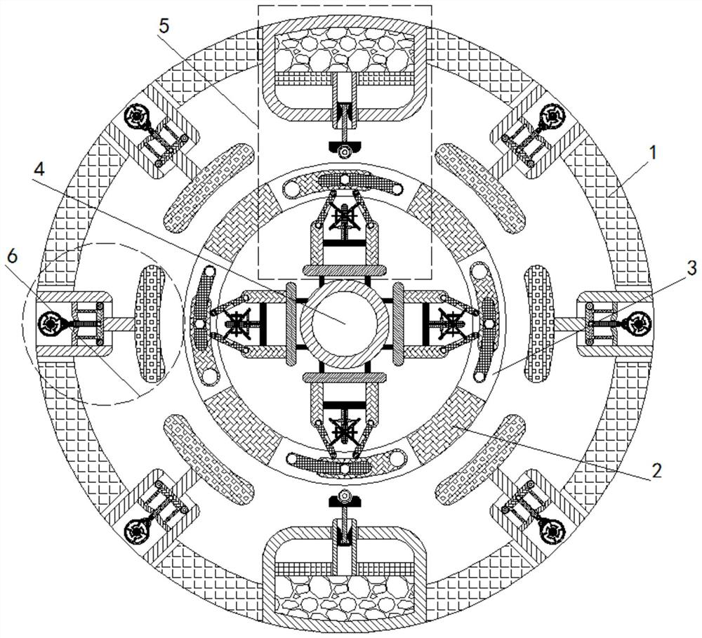
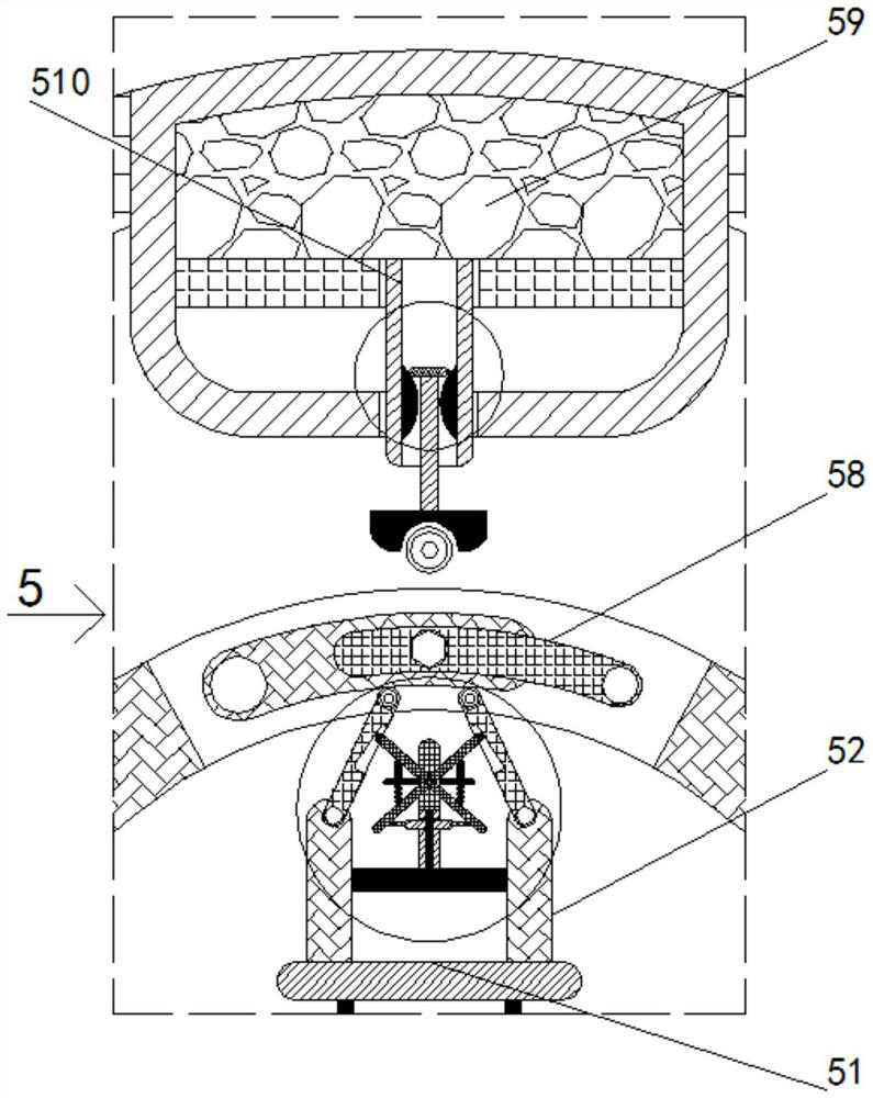
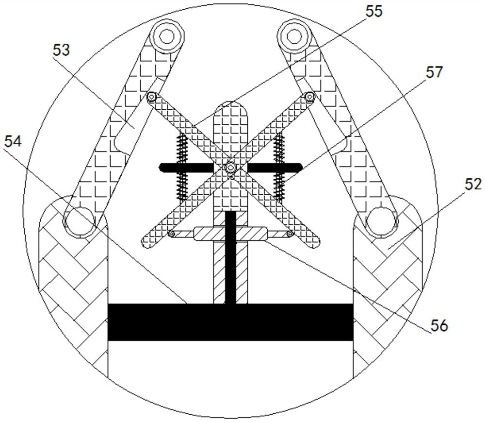
[0029] see Figure 1-4 , a device for automatically lubricating and reducing noise inside a micro-motor, including a main body 1 of lubricating equipment, a rotating disk 2 is installed inside the main body 1 of the lubricating equipment, and the outer wall of the rotating disk 2 is provided with a through hole 3, and the interior of the rotating disk 2 A water tank 4 is welded, a lubricating mechanism 5 is welded inside the main body 1 of the lubricating device, a fixing frame 51 is welded inside the lubricating mechanism 5, a rotating rod 52 is welded on the top of the fixing frame 51, and a chute 53 is opened inside the rotating rod 52, The top of the fixed frame 51 is welded with a bracket 54, the front of the bracket 54 is rotatably installed with a sliding rod 55, the left and right sides of the bracket 54 are welded with a cylinder 56, the bottom of the sliding rod 55 is welded with an elastic rod 57, and the interior of the through hole 3 is rotated and installed There...

Embodiment 2

[0032] see figure 1 and 5 -6, a device for automatically lubricating and reducing noise inside a micro-motor, comprising a main body 1 of a lubricating device, a rotating disk 2 is rotatably installed inside the main body 1 of the lubricating device, the outer wall of the rotating disk 2 is provided with a through hole 3, and the rotating disk 2 A water tank 4 is welded inside the lubricating device body 1, a noise reduction mechanism 6 is welded inside the main body 1 of the lubricating equipment, a telescopic cylinder 61 is welded inside the noise reduction mechanism 6, a runner 62 is rotatably installed inside the telescopic cylinder 61, and the inside of the telescopic cylinder 61 is welded. There is a stator 63, a blocking rod 64 is welded on the inner wall of the runner 62, a magnet 65 is welded inside the stator 63, a push rod 66 is slidably connected to the interior of the through hole 3, and a sliding rod 67 is slidably connected to the interior of the telescopic cyli...

Embodiment 3

[0035] see Figure 1-6 , a device for automatically lubricating and reducing noise inside a micro-motor, including a main body 1 of lubricating equipment, a rotating disk 2 is installed inside the main body 1 of the lubricating equipment, and the outer wall of the rotating disk 2 is provided with a through hole 3, and the interior of the rotating disk 2 A water tank 4 is welded, and the water tank 4 is made of a heat-accumulating metal material. The lubricating device main body 1 is welded with a lubricating mechanism 5 , and the lubricating device main body 1 is welded with a noise reduction mechanism 6 .

[0036]Preferably, a fixed frame 51 is welded inside the lubricating mechanism 5 , a rotating rod 52 is welded on the top of the fixed frame 51 , and a chute 53 is opened inside the rotating rod 52 . Constantly extending into the interior of the rotating rod 52, the top of the fixed frame 51 is welded with a bracket 54, the front of the bracket 54 is rotatably installed wit...


PUM


Abstract

The invention relates to the technical field of small and special electric machine lubrication, and discloses a small and special electric machine internal automatic lubrication and noise reduction device, which comprises a lubrication device main body, a rotating disc is rotatably mounted in the lubrication device main body, a through hole is formed in the outer wall of the rotating disc, and a water tank is welded in the rotating disc. And a noise reduction mechanism is welded in the lubricating equipment main body. A water solution in a water tank is evaporated into water vapor which enters an air cylinder in a rotating wheel, the air cylinder stretches out, two stop rods drive the rotating wheel to deflect, and due to the fact that a protruding arc block on the outer wall of the rotating wheel is located on one side of a push rod at the beginning, after the rotating wheel deflects, the push rod is pulled away from the circle center of a rotating disc under the action of an internal magnet; the push rod moves to drive the sliding rod to move towards the outer side of the circle center, the sound absorption plate can be far away from the rotating disc, and the effects that after the temperature rises, friction between the rotating disc and the sound absorption plate is avoided, the sound absorption plate is damaged, and the service life of the sound absorption plate is prolonged are achieved.

Description

technical field [0001] The invention relates to the technical field of micro-motor lubrication, in particular to a device for automatically lubricating the interior of a micro-motor and reducing noise. Background technique [0002] The full name of micro-special motor is micro-special motor, which refers to micro-special motor with diameter less than 16mm or rated power or special performance and special purpose. Micromotors are often used in control systems to realize functions such as detection, calculation, amplification, execution or conversion of electromechanical signals or energy. [0003] During the use of the micro motor, when the degree of lubrication of the internal parts is insufficient, the internal temperature of the motor will rise, which is not conducive to the long-term operation of the micro motor, and the noise reduction equipment inside the micro motor will absorb sound during use. The constant frictional contact between the board and the internal rotati...

Claims


Application Information

Patent Timeline
Patent Type & Authority Applications(China)
IPC IPC(8): F16N11/08H02K5/24
CPCF16N11/08H02K5/24
Inventor 王仁刚
Owner 徐州力达电机技术有限公司
Why Eureka
Try Eureka