Blind hole spline coaxiality measuring method and measuring device thereof
A technology of coaxiality measurement and coaxiality, which is applied in angle/taper measurement and other directions, can solve the problems of low coaxiality measurement efficiency and large measurement error, and achieve the effect of simple and convenient measurement method, low cost and small error
- Summary
- Abstract
- Description
- Claims
- Application Information
AI Technical Summary
Problems solved by technology
Method used
Image

Examples
Embodiment 1
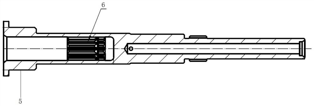
[0030] refer to figure 1 The shaft is to be measured as the elongated spindle, and the outer side of the end of the axis is provided with a reference outer circle 5, and the top end of the reference outer circle 5 is provided between the top end of the pending axis, the outer diameter of the limit ring is greater than the outer circle. 5 outer diameter; there is a deeper blind hole along the axial direction of the shaft to be measured, and in the bottom of the blind hole 6, the inner spline 6 and the reference outer circle 5 are cantilever on the elongated spindle. Distribution, in assembly, the coaxial degree between the inner spline 6 and the reference outer circle 5 is required, that is, the blind hole spline is the same as the shaft, and the specialty of the splines and the reference outer circle structure. Moreover, the product requires the same shaft degree accuracy, and it is necessary to mark a range of homagical values. The coaxial measurement method and the measurement d...
Embodiment 2
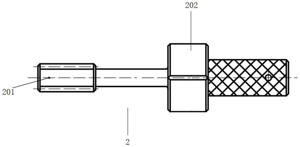
[0051] refer to figure 2 and image 3 A blind hole spline coaxial measuring device, including the measuring body 1 and the spline mandrel 2, the measurement body 1 is opened, the step hole includes a guide hole 101 and a positioning hole 102 that open in the coaxial opening, and the guide hole 101 The inner diameter is larger than the inner diameter of the positioning hole 102, and the guide hole 101 is located at the top of the positioning hole 102; the spline core 2 includes an outer spline 201 and a guide station 202 located at the end of the outer splines 201, preferably a cylinder. An exhaust tank is opened on the outer side wall of the guide station to ensure that the spline core rod 2 is in line with the inner spline blind hole, and the air in the blind hole in the blind hole is discharged in time, the top surface and the guide station of the outer spline 201 201 202 is provided with a connecting axis, the spline of the outer spline 201 is designed according to the spline in...
Embodiment 3
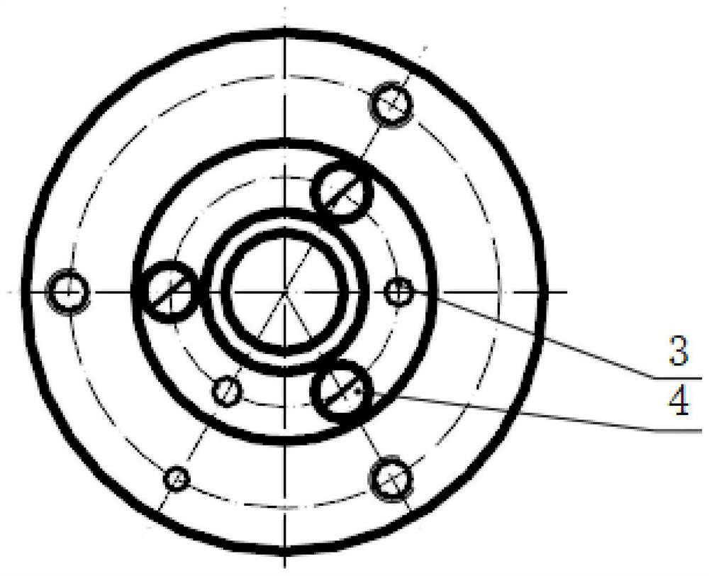
[0060] refer to Figure 4 Unlike Example 1, the measuring body 1 includes a guide plate 103 and a positioning body 104, and the guide hole 101 is opened on the guide plate 103, and the positioning hole 102 is opened on the positioning body 104, and the reference outer circle 5 is passed through the positioning hole 102 and the positioning body. 104 mating, the limit ring is in contact with the upper end surface of the positioning body 104, and the limit ring is located in the guide hole 101 in the guide plate 103, and there is a plurality of corresponding pin holes and threaded holes, and the pockets, and the pockets 104 are opened. The corresponding pin block 3 and the screw 4 are connected to the threaded holes, and the guide plate 103 and the positioning body 104 are steadily joined by the pin block 3 and the screw 4 such that the guide hole 101 and the positioning hole 102 can maintain coaxial setting;
[0061] The pin holes and screw holes are disposed about the center interva...
PUM
 Abstract
Description
Claims
Application Information