Phased array receiving system of RSU based on DDS

A receiving system and phased array technology, which is applied in the field of RSU phased array receiving system, can solve problems such as ETC adjacent channel interference, difficulty in precise beam adjustment, expensive phase shifters and attenuators, etc. Adjacent channel interference and car-following interference, realize fine phase shift and fine amplitude modulation, and reduce material cost

Pending Publication Date: 2022-04-15
广州市埃特斯通讯设备有限公司
View PDF0 Cites 0 Cited by
  • Summary
  • Abstract
  • Description
  • Claims
  • Application Information

AI Technical Summary

Problems solved by technology

[0006] With the application and promotion of ETC, there are more and more ETC parallel lanes, and the problems of ETC adjacent lane interference and car-following interference have been prominent, which have always plagued the development of ETC. In order to better dynamically control the receiving beam range of RSU, an analog phase The phased array receiving beam scanning technology, the phased array receiving beam scanning is realized by controlling the phase and amplitude of the multi-channel 5.8G frequency band RF signal, the phase is controlled by a phase shifter, and the amplitude is controlled by an attenuator; however, The 5.8G frequency band phase shifter and attenuator are very expensive, and each channel needs to be used, which greatly increases the material cost of the RSU
[0007] In addition, phase shifters and attenuators use limited steps (usually less than or equal to 64 levels) to phase shift and attenuate signals, which cannot achieve precise phase shift and precise amplitude modulation, so it is difficult to precisely adjust the beam. This application Provide a DDS-based RSU phased array receiving system

Method used


Image

  • Phased array receiving system of RSU based on DDS
  • Phased array receiving system of RSU based on DDS
  • Phased array receiving system of RSU based on DDS

Examples


Embodiment Construction

[0023] The DDS-based RSU phased array receiving system of the present invention is mainly applicable to ETC.

[0024] refer to figure 1 , figure 2 , image 3 and Figure 4 , the DDS-based RSU phased array receiving system of the present invention will be described in detail below.

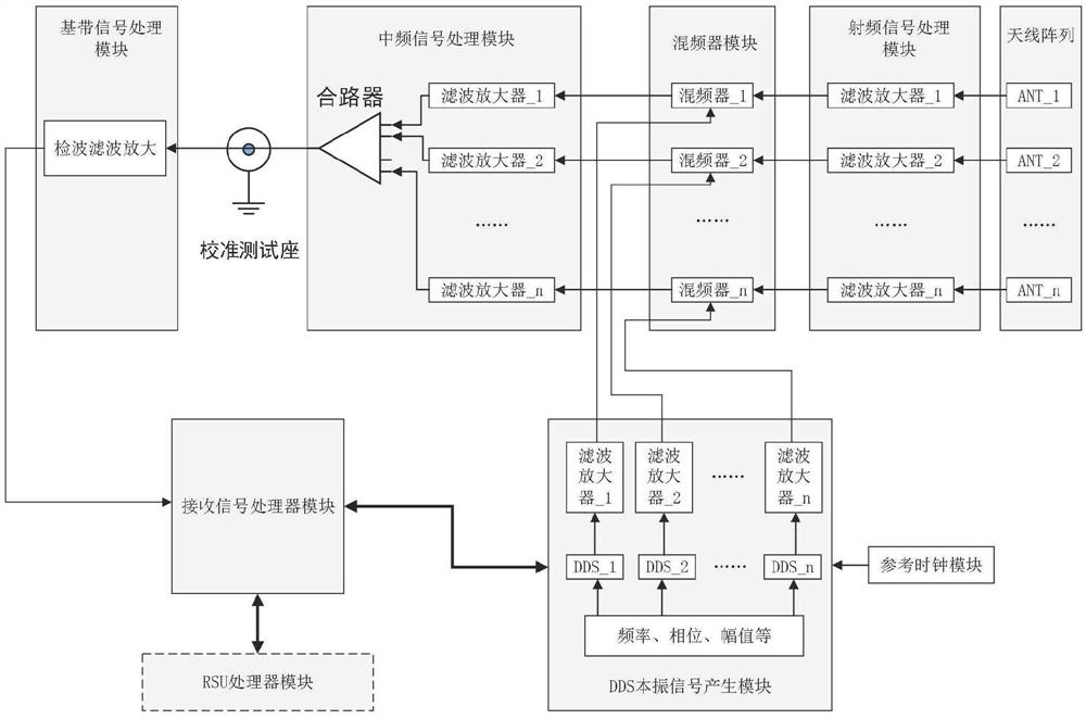
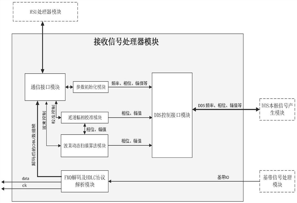
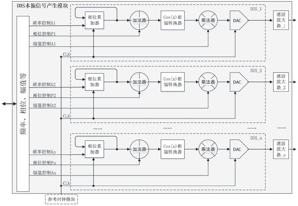
[0025] refer to figure 1, a DDS-based RSU phased array receiving system in this embodiment includes an antenna array, a radio frequency signal processing module, a mixer module, a DDS local oscillator signal generation module, a reference clock module, an intermediate frequency signal processing module, and a calibration test Seat, baseband signal processing module, receiving signal processor module, RSU processor module, described RSU processor module is connected with described receiving signal processor module to realize parameter configuration and obtain the OBU data that described receiving signal processor module receives Frame information, the antenna array, the radio frequency signal ...


PUM


Abstract

The invention provides a DDS-based RSU phased array receiving system, which is characterized by comprising an antenna array, a radio frequency signal processing module, a frequency mixer module, a DDS local oscillator signal generation module, a reference clock module, an intermediate frequency signal processing module, a calibration test seat, a baseband signal processing module, a received signal processor module and an RSU processor module, the DDS local oscillator signal generation module is connected with the mixer module, and the phase and amplitude of a multi-channel intermediate frequency signal after frequency mixing are controlled by independently controlling the phase and amplitude of a local oscillator signal generated by a multi-channel DDS of the DDS local oscillator signal generation module, so that the multi-channel intermediate frequency signal generates an expected superposition effect after passing through a combiner; according to the RSU phased array receiving system based on the DDS, the problems of ETC adjacent channel interference and vehicle following interference can be well solved, and the material cost of the RSU is reduced.

Description

technical field [0001] The invention relates to a phased array receiving system, in particular to a DDS-based RSU phased array receiving system in the field of ETC. Background technique [0002] ETC: (Electronic Toll Collection) non-stop toll collection system is the most advanced road and bridge toll collection method in the world at present, through the special microwave short-range between the vehicle electronic tag installed on the vehicle windshield and the microwave antenna on the ETC lane of the toll station Communication, deducting the amount on the user card or using computer networking technology to carry out background settlement processing with the bank, so as to achieve the purpose of paying road and bridge tolls without stopping when vehicles pass through road and bridge toll stations. ETC is an advanced electronic toll collection technology. At the entrance and exit of the ramp and the sign station of the main line, both are ETC application models in the close...

Claims


Application Information

Patent Timeline
Patent Type & Authority Applications(China)
IPC IPC(8): G07B15/06H04B7/08H04B10/2575H04B10/291H04B10/294H04B10/60H04L69/16
Inventor 黄小岛
Owner 广州市埃特斯通讯设备有限公司
Why Eureka
Try Eureka