Dry-type box capacitor potting process

A technology for capacitors and boxes, which is applied in the field of potting technology for dry-type box capacitors, can solve the problems that the potting process cannot meet the requirements, and achieve the effects of ensuring partial discharge performance, improving reliability and service life, and ensuring insulation performance

Pending Publication Date: 2022-04-15
HERONG ELECTRIC
View PDF0 Cites 0 Cited by
  • Summary
  • Abstract
  • Description
  • Claims
  • Application Information

AI Technical Summary

Problems solved by technology

At present, high-voltage power capacitors are oil-immersed insulation and the potting process of low-voltage power electronic capacitors cannot meet the requirements.

Method used


Image

  • Dry-type box capacitor potting process
  • Dry-type box capacitor potting process
  • Dry-type box capacitor potting process

Examples


Embodiment Construction

[0023] The present invention will be described in detail below in conjunction with the accompanying drawings and specific embodiments.

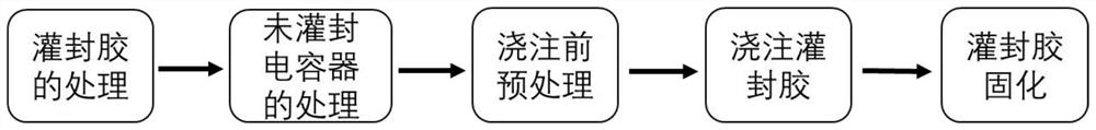
[0024] Dry box capacitor potting process of the present invention, such as figure 1 As shown, the following steps are included: treatment of the potting compound, treatment of the unpotted capacitor, pretreatment before pouring, pouring of the potting compound, and curing of the potting compound.

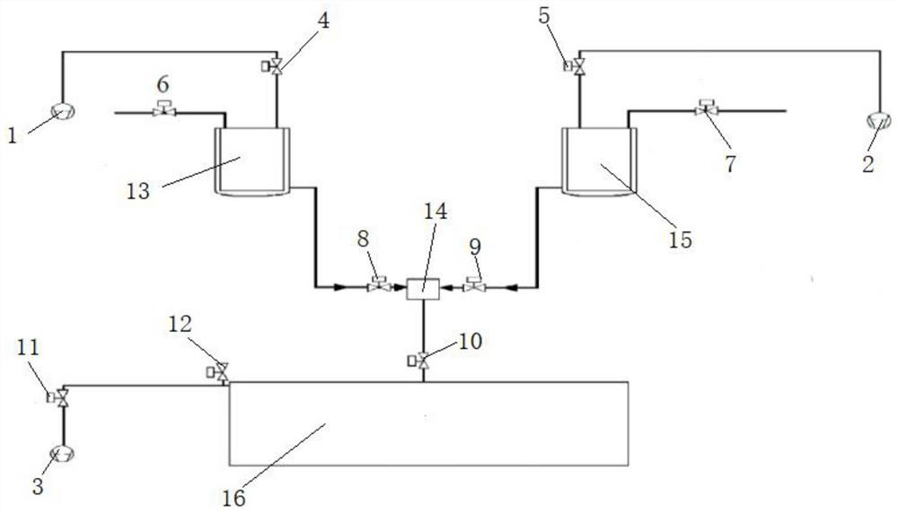
[0025] Such as figure 2 As shown, turn on the vacuum pump A1 and vacuum pump B2, the evacuation valve A4 and the evacuation valve B5, and when the air pressure in the vacuum tank A13 and the vacuum tank 15 is 80-150Pa, open the feed valve A6 and the feed valve B7, respectively pour the potting glue The A and B components of the potting glue are pumped into the vacuum tank A13 and the vacuum tank B15 for stirring, and the A and B components of the potting glue are all pumped into the vacuum tank A13 and the vacuum tank B15, and then the feed valve...


PUM


Abstract

The invention discloses a dry box capacitor potting process. The dry box capacitor potting process sequentially comprises the steps of potting adhesive treatment, non-potting capacitor treatment, pretreatment before pouring, potting adhesive pouring and potting adhesive curing. The component A and the component B of the pouring sealant are subjected to constant-temperature vacuum pumping treatment before pouring and the capacitor in the pouring tank is subjected to constant-temperature vacuum pumping treatment, the pouring process is carried out in a vacuum state, and constant-temperature pressure maintaining treatment is carried out after pouring is completed, so that almost no bubble exists in the pouring sealant, and the insulating property of the capacitor is ensured. The excessive pouring sealant is poured through the funnel, so that an air gap between the pouring sealant and the shell in the curing shrinkage process of the pouring sealant is filled, the partial discharge performance of the capacitor is ensured, and the reliability and the service life of the capacitor are greatly improved.

Description

technical field [0001] The invention belongs to the technical field of DC support capacitors for flexible DC transmission converter valves, and relates to a dry-type box capacitor potting process. Background technique [0002] The DC support capacitor for the flexible DC transmission converter valve is the core component of the converter valve group in the flexible HVDC transmission technology, and its function is to support and stabilize the voltage of the sub-module and provide a voltage source. [0003] In order to meet the application requirements of the flexible HVDC converter valve group, the DC support capacitor for the flexible HVDC converter valve needs to be a dry-type box structure, and has extremely high requirements for the pole-to-shell insulation performance and partial discharge performance. At present, the high-voltage power capacitors are oil-immersed insulation and the potting process of low-voltage power electronic capacitors cannot meet the requirements....

Claims


Application Information

Patent Timeline
IPC IPC(8): H01G13/00
Inventor 石泽祥葛娟娟崔江丽解冲肖果
Owner HERONG ELECTRIC
Why Eureka
Try Eureka