Draw-out type low-voltage power distribution cabinet based on spontaneous combustion prevention protection

A technology of withdrawable and power distribution cabinets, which is applied in the direction of electrical components, electromechanical devices, electric components, etc., and can solve problems such as economic loss, inconvenient drawing of the movable cabinet body, and inconvenience in practical use.

Active Publication Date: 2022-04-15
卡雷迪电气(常州)有限公司
View PDF4 Cites 3 Cited by
  • Summary
  • Abstract
  • Description
  • Claims
  • Application Information

AI Technical Summary

Problems solved by technology

[0004] In view of the above situation, in order to overcome the defects of the prior art, the present invention provides a draw-out type low-voltage power distribution cabinet based on anti-spontaneous combustion protection, which effectively solves the problem that it is inconvenient to pull out the main body of the pull-out movable cabinet as a whole in the above-mentioned background technology. Moreover, there is a lack of corresponding anti-spontaneous combustion protection mechanism in the power distribution cabinet. When the power distribution cabinet is running, the high temperature is likely to cause spontaneous combustion, resulting in economic losses, and it is not convenient for practical use.

Method used


Image

  • Draw-out type low-voltage power distribution cabinet based on spontaneous combustion prevention protection
  • Draw-out type low-voltage power distribution cabinet based on spontaneous combustion prevention protection
  • Draw-out type low-voltage power distribution cabinet based on spontaneous combustion prevention protection

Examples


Embodiment 1

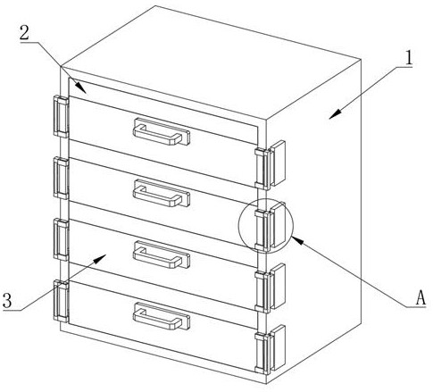
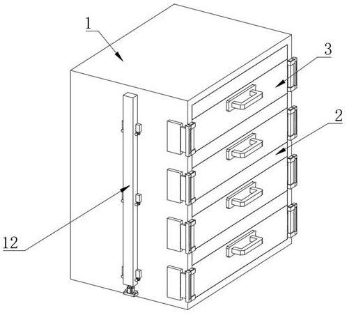
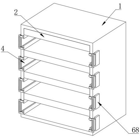
[0036] Embodiment one, by Figure 1 to Figure 11 It is given that the present invention includes a withdrawable low-voltage power distribution cabinet body 1, the withdrawable low-voltage power distribution cabinet body 1 is a cavity structure with one side opening, and several heat dissipation protection box bodies 2 are arranged in the withdrawable low-voltage power distribution cabinet body 1. The bottom of the heat dissipation protection box body 2 is provided with a pull-out movable cabinet body 3, the heat dissipation protection box body 2 is fixedly connected with the inner wall of the withdrawable low-voltage power distribution cabinet body 1, and the pull-out movable cabinet body 3 is a cavity structure with an opening at the top. A number of chutes 4 are provided on both sides of the main body 1 of the type low-voltage power distribution cabinet. Both are fixedly connected with a slider 5, the slider 5 is located in the chute 4, the drawable movable cabinet body 3 an...

Embodiment 2

[0038] Embodiment two, on the basis of embodiment one, by figure 1 , Figure 6 and Figure 7 Given, two second worms 20 of the transmission unit are arranged in the heat dissipation protection box body 2, one end of the second worm 20 is connected with one side inner wall of the heat dissipation protection box body 2 through the fourth bearing 22, and one end of the second worm 20 There is a second worm wheel 21 on the side, the second rotating shaft 17 runs through the second worm wheel 21, and the second rotating shaft 17 and the second worm wheel 21 are fixedly connected, and one end of the second worm 20 is fixedly connected with a second bevel gear 23, and the heat dissipation protection box The body 2 is provided with two third bevel gears 24, the first worm 9 runs through the third bevel gear 24, and the first worm 9 and the third bevel gear 24 are fixedly connected, the second bevel gear 23 and the third bevel gear The bevel gear 24 is meshed, the second worm 20 is m...

Embodiment 3

[0040]Embodiment three, on the basis of embodiment one, by figure 1 , Figure 5 and Figure 6 Given, the drawable locking assembly includes a first card slot 26 opened at the bottom of the heat dissipation protection box body 2, a first clamping plate 27 is provided in the drawable movable cabinet body 3, and a side inner wall of the drawable movable cabinet body 3 is provided with The second rectangular hole 28, the second rectangular hole 28 is provided with a first connecting plate 30, a side of the drawer movable cabinet body 3 is provided with a movable seat 29, and the two sides of the first connecting plate 30 are connected with the first clamping plate 27 respectively. It is fixedly connected with the movable seat 29, and the bottom of the first clamping plate 27 is provided with a fixed strip 31, and one side of the fixed strip 31 is fixedly connected with the inner wall of the drawer movable cabinet body 3, and the top of the fixed strip 31 is connected with the top...


PUM


Abstract

The invention relates to the technical field of draw-out type low-voltage power distribution cabinets, discloses a draw-out type low-voltage power distribution cabinet based on spontaneous combustion prevention protection, and solves the problems that a draw-out movable cabinet body is inconvenient to draw out as a whole, a corresponding spontaneous combustion prevention protection mechanism is lacked in the power distribution cabinet, spontaneous combustion is easily caused by high temperature during operation of the power distribution cabinet, economic loss is caused and the like. The draw-out type low-voltage power distribution cabinet comprises a draw-out type low-voltage power distribution cabinet body, the draw-out type low-voltage power distribution cabinet body is of a cavity structure with an opening in one side, a plurality of heat dissipation protection box bodies are arranged in the draw-out type low-voltage power distribution cabinet body, and a draw-out movable cabinet body is arranged at the bottom of each heat dissipation protection box body; the heat dissipation protection box body is fixedly connected with the inner wall of the draw-out type low-voltage power distribution cabinet body, and the draw-out movable cabinet body is of a cavity structure with an opening in the top end. The interior of the draw-out movable cabinet body is cooled, the possibility of spontaneous combustion due to high temperature is reduced, and the whole draw-out movable cabinet body can be conveniently drawn out of the draw-out type low-voltage power distribution cabinet body.

Description

technical field [0001] The invention belongs to the technical field of withdrawable low-voltage power distribution cabinets, in particular to a withdrawable low-voltage power distribution cabinet based on anti-spontaneous combustion protection. Background technique [0002] Power distribution cabinets are divided into power distribution cabinets, lighting distribution cabinets, and metering cabinets, and are the final equipment of the power distribution system. The power distribution cabinet is a general term for the motor control center. The power distribution cabinet is used in the occasions where the load is relatively scattered and there are few circuits; the motor control center is used in the occasions where the load is concentrated and there are many circuits. They distribute the electric energy of a certain circuit of the upper-level power distribution equipment to the nearest load. This level of equipment shall provide protection, monitoring and control of the loa...

Claims


Application Information

Patent Timeline
Patent Type & Authority Applications(China)
IPC IPC(8): H02B1/36H02B1/56H02K7/116H02K5/00
CPCH02B1/36H02B1/565H02K7/1166H02K5/00Y02A30/14
Inventor 丁军
Owner 卡雷迪电气(常州)有限公司
Why Eureka
Try Eureka