
Radio frequency switch circuit

A radio frequency switch and circuit technology, applied in the field of radio frequency, can solve the problem that the radio frequency switch circuit is easily damaged

Pending Publication Date: 2022-04-15
RUIPAN MICROELECTRONICS TECH (SHANGHAI) CO LTD
View PDF0 Cites 0 Cited by
  • Summary
  • Abstract
  • Description
  • Claims
  • Application Information

AI Technical Summary

Problems solved by technology

[0004] The embodiment of the present invention provides a radio frequency switch circuit to solve the problem that the radio frequency switch circuit is easily damaged

Method used


Image

  • Radio frequency switch circuit
  • Radio frequency switch circuit
  • Radio frequency switch circuit

Examples


Embodiment Construction

[0032] The following will clearly and completely describe the technical solutions in the embodiments of the present invention with reference to the accompanying drawings in the embodiments of the present invention. Obviously, the described embodiments are some of the embodiments of the present invention, but not all of them. Based on the embodiments of the present invention, all other embodiments obtained by persons of ordinary skill in the art without creative efforts fall within the protection scope of the present invention.

[0033] It should be understood that the invention can be embodied in different forms and should not be construed as limited to the embodiments set forth herein. Rather, these embodiments are provided so that this disclosure will be thorough and complete, and will fully convey the scope of the invention to those skilled in the art. In the drawings, the size and relative sizes of layers and regions may be exaggerated for clarity, and like reference numer...


PUM


Abstract

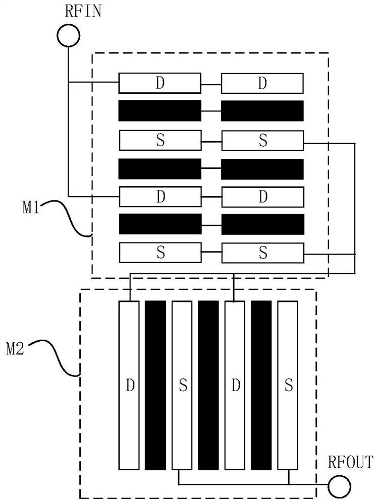
The invention discloses a radio frequency switch circuit which comprises a signal input end, a signal output end and a transistor stack circuit. The transistor stack circuit comprises N transistors, the second end of the (i-1) th transistor is connected with the first end of the ith transistor, and the second end of the ith transistor is connected with the signal output end; the calculation formula of the total width of each transistor is W = FW * F * M, W is the total width of the transistor, FW is the width of the grid comb fingers, F is the number of the grid comb fingers, and M is the number of the parallel comb finger tubes; the W value in the first transistor is the maximum, and the W value in the Nth transistor is the minimum; the FW value of each transistor is configured to enable the breakdown voltage of the transistor to be larger than the peak voltage borne by the two ends of the transistor, and the breakdown voltage is in negative correlation with the FW value. According to the technical scheme, the y-punch voltage of each transistor is larger than the peak voltage borne by the two ends of the transistor, and the effect of preventing the radio frequency switch circuit from being damaged is achieved.

Description

technical field [0001] The invention relates to the field of radio frequency technology, in particular to a radio frequency switch circuit. Background technique [0002] With the development of mobile communication technology, multiple communication standards coexist. Therefore, the RF front-end architecture generally integrates RF power amplifiers of multiple modes and different frequency bands, and selects the required RF power amplifier through the RF switch circuit. Establish the receiving and transmitting channels of radio frequency signals to realize switching between different communication networks. [0003] At present, most radio frequency front-end architectures include multiple radio frequency switch circuits, and each radio frequency switch circuit is composed of multiple radio frequency switch devices connected in series. However, when the radio frequency switch circuit is in operation, the voltages distributed on the various radio frequency switch devices (tra...

Claims


Application Information

Patent Timeline
IPC IPC(8): H03K17/041H03K17/687
Inventor 王蕴洲王欢奉靖皓倪建兴
Owner RUIPAN MICROELECTRONICS TECH (SHANGHAI) CO LTD
Learn More