Steam turbine drainage device

A steam turbine and water-repellent technology, which is applied in the connection with fluid cut-off device, mechanical equipment, flange connection, etc., can solve the problems of complex connection structure between the steam turbine drain and the water pipe, unfavorable rapid drainage, low drainage efficiency, etc., and achieve improvement The efficiency of assembly production, the improvement of practical convenience, and the effect of rapid assembly and disassembly

Pending Publication Date: 2022-04-19
INNER MONGOLIA MENGDA POWER GENERATION CO LTD +1
View PDF0 Cites 0 Cited by
  • Summary
  • Abstract
  • Description
  • Claims
  • Application Information

AI Technical Summary

Problems solved by technology

[0005] Therefore, the technical problem to be solved by the present invention is that the existing steam turbine drainage heat well has defects in drainage, and the drainage efficiency is low, which is not conducive to the current rapid drainage requirements. In addition, the connection structure between the steam turbine outlet and the water pipe is more complicated. trouble

Method used


Image

  • Steam turbine drainage device
  • Steam turbine drainage device
  • Steam turbine drainage device

Examples


Embodiment 1

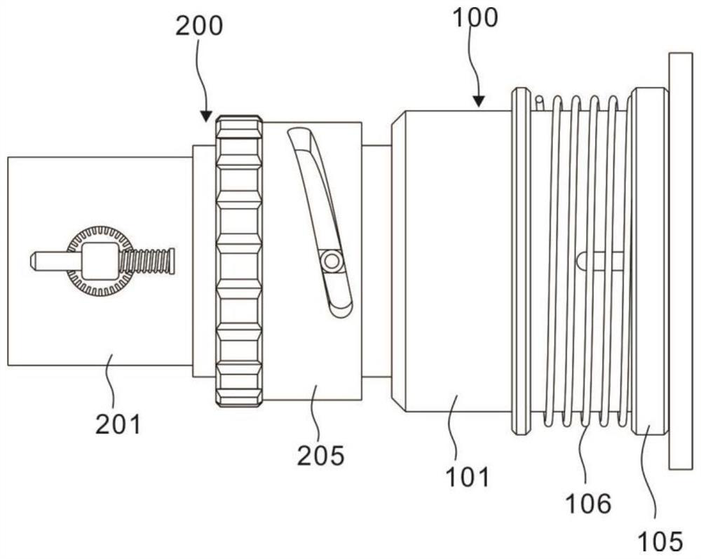
[0034] refer to Figure 1~2 , 5, 6, this embodiment provides a steam turbine drainage device, including a fixed joint 100 and a movable joint 200, wherein the fixed joint 100 is fixedly installed at the drain of the steam turbine, and the movable joint 200 is connected to the movable joint 200 before being connected to the drain pipeline.

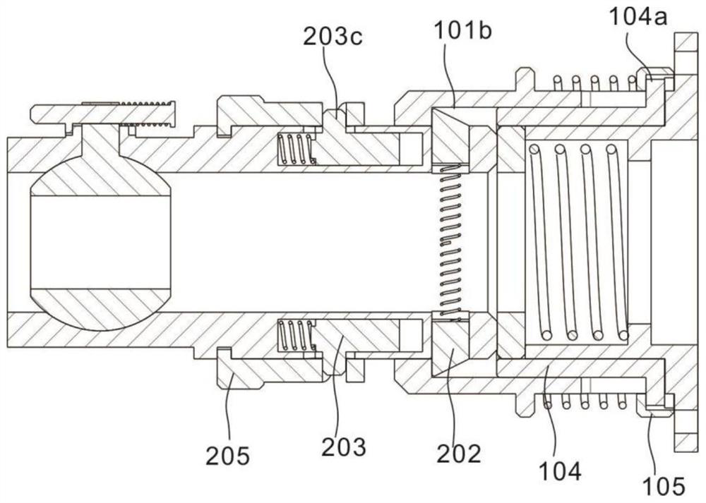
[0035]Wherein, the fixed joint 100 includes a connecting seat 101, the connecting seat 101 is a rotating body, the connecting seat 101 is provided with a first through hole 101a through, the connecting seat 101 is provided with a connecting flange 101d, and the connecting flange 101d is fixedly connected to the drain port of the steam turbine , the first through hole 101a communicates with the steam turbine drain, and the first through hole 101a is provided with an annular groove groove 101b; the inner diameter of the annular groove groove 101b is larger than the inner diameter of the first through hole 101a, and the connecting head 201 is ...

Embodiment 2

[0047] refer to Figure 1-8 , is the second embodiment of the present invention, this embodiment is based on the previous embodiment, and differs from the previous embodiment in that:

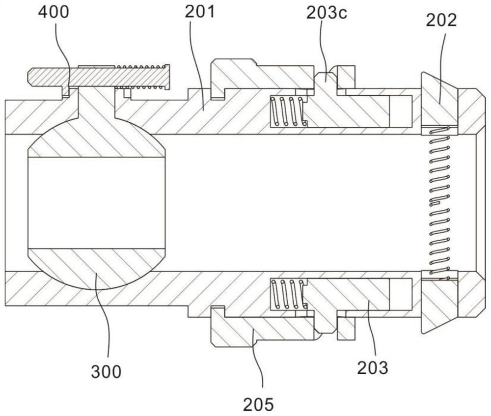
[0048] Wherein, the connection seat 101 is provided with a first through hole 101a penetrating, and the first through hole 101a is used to connect with the connector 201; the first through hole 101a is provided with a ring groove groove 101b, and the ring groove groove 101b The inner diameter is greater than the inner diameter of the first through hole 101a; the outer diameter of the connector 201 is consistent with the inner diameter of the first through hole 101a, and the connector 201 is provided with a second through hole 201a that passes through. When the connector 201 is connected to the connection seat 101, the second The second through hole 201a communicates with the first through hole 101a to deliver gas; the side of the second through hole 201a is provided with a chute 201b extending ...


PUM


Abstract

The steam turbine drainage device comprises a fixed connector, the fixed connector comprises a connecting base, the connecting base is provided with a connecting flange, and the connecting flange is fixedly connected to a steam turbine drainage opening; the movable connector comprises a connector connected with the connecting base in a matched mode, the connector is provided with a second through hole penetrating through the connector, a sliding groove extending in the radial direction is formed in the side face of the second through hole, and a sliding block is arranged in the sliding groove. The connecting seat is sleeved with an annular ring, a deep groove is formed in the inner side face of the annular ring, the deep groove is annular, and the fixing pin is embedded into the deep groove; the steam turbine drainage port is connected with the drainage pipeline through the fixed connector and the movable connector, rapid assembly and disassembly of the steam turbine drainage pipe can be achieved, the assembly production efficiency and actual use convenience of the drainage pipe are greatly improved, and the problem that a conventional steam turbine drainage pipe is inconvenient to assemble and disassemble is solved.

Description

technical field [0001] The invention relates to the field of steam turbine drainage, in particular to a steam turbine drainage device. Background technique [0002] The small steam turbine in a thermal power plant refers to the equipment used to supply electric energy to the auxiliary equipment of the large steam turbine, such as the boiler feed water pump, to reduce the power consumption rate of the plant, convert the secondary steam into electric energy, and reduce the total loss of the power plant. Drainage is the condensed water produced by steam in the pipeline due to the pressure and temperature drop. Drainage should be discharged in time, otherwise it will not only absorb the heat of steam in the pipe, affect the flow of steam, but also cause serious water hammer phenomenon and cause serious consequences. The existing steam turbine drainage heat well has defects in drainage, and the drainage efficiency is low, which is not conducive to the current rapid drainage requ...

Claims


Application Information

Patent Timeline
Patent Type & Authority Applications(China)
IPC IPC(8): F16L37/086F16L29/00F16L23/024F16L23/16
CPCF16L37/086F16L29/002F16L23/024F16L23/16
Inventor 孙启德刘富栋刘志伟李军虎乔燕雄王海涛王飞焦利峰岳岚
Owner INNER MONGOLIA MENGDA POWER GENERATION CO LTD
Why Eureka
Try Eureka