
Control circuit, switching power supply circuit and control method

A control circuit and controller technology, applied in control/regulation systems, high-efficiency power electronic conversion, electrical components, etc., can solve problems such as ghost hands on mobile phone screens, time offset of drain-source voltage oscillation, and unstable switching frequency. Achieve the effects of improving efficiency, reducing switching power consumption, and weakening the influence of electromagnetic interference

Pending Publication Date: 2022-04-19
HANGZHOU SILAN MICROELECTRONICS
View PDF0 Cites 1 Cited by
  • Summary
  • Abstract
  • Description
  • Claims
  • Application Information

AI Technical Summary

Problems solved by technology

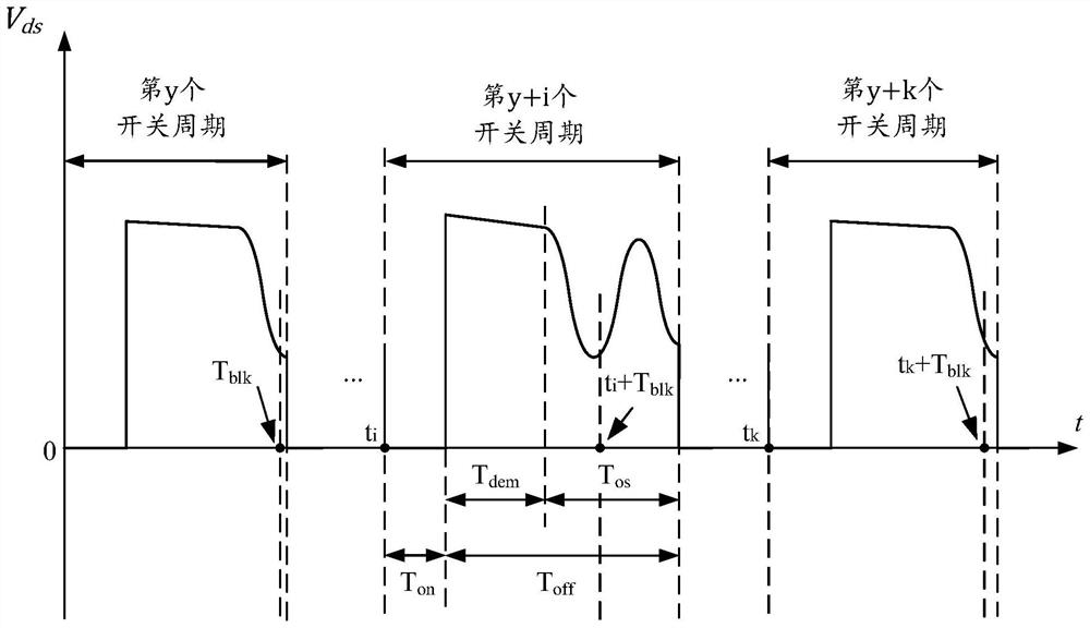
[0007] However, although the above-mentioned traditional quasi-resonant control technology can realize valley-bottom conduction, as the output power or other parameters of the switching power supply change, the speed at which the transformer consumes energy after the power tube is turned off may change, resulting in drain-source voltage The timing of onset of oscillations shifts
If the masking time T blk is a fixed value, the drain-source voltage may drop during the blanking time T blk Inner or valley detection window time T w The drive controller may turn on the power transistor at different valleys after the start of the oscillation, so the valley "lock" cannot be achieved, that is, for any output power, the drive controller cannot guarantee that it is always at the first valley Turn on the power tube at x valleys (x is a fixed value and a natural number greater than 0), even in the steady state of the switching power supply, the conduction moment of the power tube may switch back and forth periodically between adjacent valleys
Since there is a resonant period interval between adjacent valleys, this defect may lead to a large change in the switching cycle (that is, the "jumping valley" phenomenon), which makes the switching frequency unstable and the switching power supply has poor anti-electromagnetic interference performance.
Especially in applications such as mobile phone fast charging products, if the switching power supply adopts the traditional quasi-resonant technology without "locking" the bottom, then operating the mobile phone while the mobile phone is charging is likely to cause the phenomenon of "ghost hands" on the mobile phone screen (that is, user Uncontrollable and unexpected actions such as clicking or swiping)

Method used


Image

  • Control circuit, switching power supply circuit and control method
  • Control circuit, switching power supply circuit and control method
  • Control circuit, switching power supply circuit and control method

Examples


Embodiment Construction

[0054] Various embodiments of the invention will be described in more detail below with reference to the accompanying drawings. In the various drawings, the same elements are denoted by the same or similar reference numerals. For the sake of clarity, various parts in the drawings have not been drawn to scale.

[0055] Unless otherwise specified, expressions such as "off time", "on time", "switching cycle", "shielding time", and "bottom detection window time" in this disclosure all represent corresponding stages and corresponding time lengths.

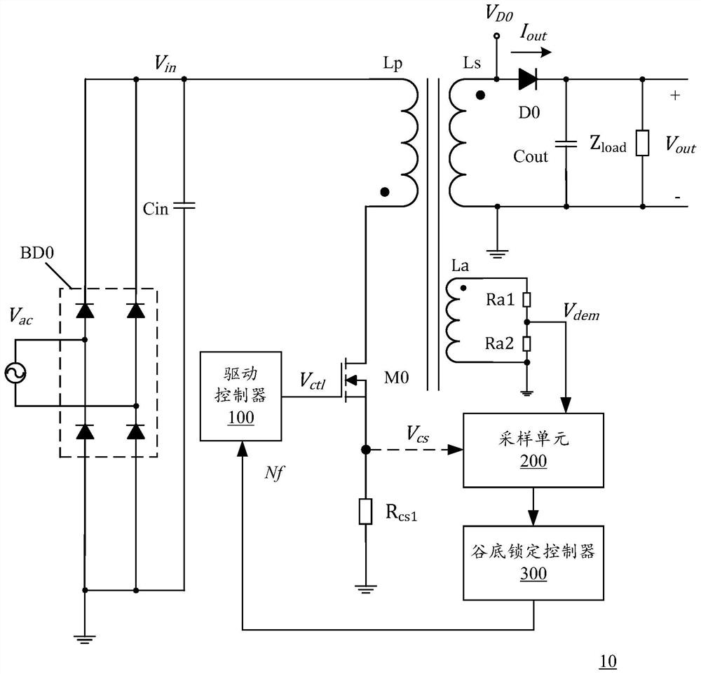
[0056] In the description of the present disclosure, the symbol of each coil can also represent the inductance value of the coil. For example, the inductance value of the primary coil Lp is expressed as Lp in the formula, the inductance value of the secondary coil Ls is expressed as Ls in the formula, and the inductance value of the auxiliary coil La is expressed as La in the formula. Similarly, the symbol of each resistor can represe...


PUM


Abstract

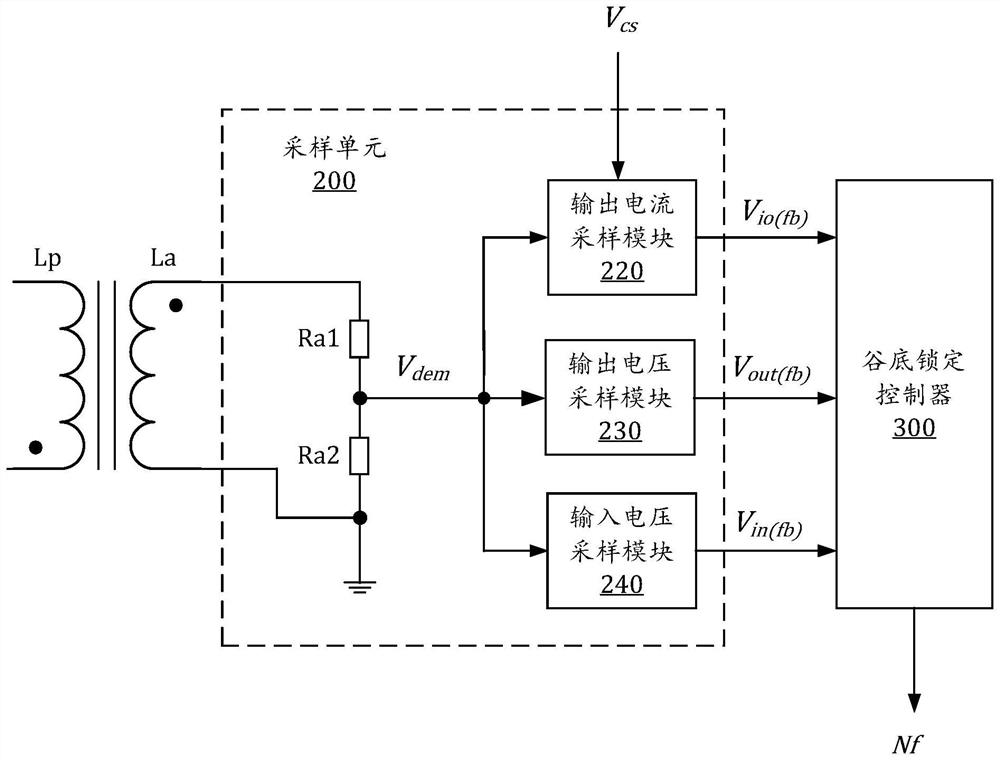
The invention discloses a control circuit of a power converter, a control method of the control circuit, a switching power supply circuit and a driving control method. The control circuit comprises a sampling unit used for sampling an input voltage, an output voltage and an output current of the power converter to obtain a plurality of sampling signals; the valley bottom locking controller is electrically connected with the sampling unit and adaptively selects the most adaptive valley bottom matched with the current input and output specification according to the plurality of sampling signals; and the driving controller is used for conducting the power tube at the most adaptive valley bottom after the demagnetization of the power converter is finished. The invention provides a new quasi-resonance control technology which can realize valley bottom locking and adaptive adjustment of each input and output specification, thereby avoiding the phenomenon of'valley bottom jumping 'while adapting to various input and output specifications, and improving the efficiency and the anti-electromagnetic interference performance.

Description

technical field [0001] The present disclosure relates to power electronics technology, in particular, to a control circuit of a power converter and a control method thereof, a switching power supply circuit and a drive control method. Background technique [0002] Switching power supply has the advantages of easy control, high efficiency, small size, and good reliability. It is widely used in TV power supplies, mobile phone chargers, LEDs, industrial instruments, power adapters and other equipment. In a switching power supply, increasing the switching frequency of the power switching device can bring many beneficial effects, such as reducing the audio noise of the switching power supply and improving the dynamic response speed, and the increase of the switching frequency also helps to reduce the size and weight of the circuit. Therefore, increasing the switching frequency is an important direction for the development of switching power supply technology. However, since the ...

Claims


Application Information

Patent Timeline
Patent Type & Authority Applications(China)
IPC IPC(8): H02M3/335H02M1/00H02M1/32H02M1/44
CPCH02M3/33523H02M1/00H02M1/32H02M1/44Y02B70/10
Inventor 吴剑郭瑭瑭夏原野
Owner HANGZHOU SILAN MICROELECTRONICS
Learn More