
Conveying equipment for building top surface greening

A technology for conveying equipment and buildings, which is applied in the field of conveying equipment for greening the top of buildings, can solve the problems of time-consuming, labor-intensive, and low work efficiency.

Pending Publication Date: 2022-04-22
陈 国金
View PDF7 Cites 0 Cited by
  • Summary
  • Abstract
  • Description
  • Claims
  • Application Information

AI Technical Summary

Problems solved by technology

[0005] In order to overcome the shortcomings of using the existing construction device for greening on the top of the building, which requires the user to manually push, time-consuming and labor-intensive, and low work efficiency, the purpose of the present invention is to provide a device that can automatically transport and lay the lawn. Conveying equipment for greening on top of buildings

Method used


Image

  • Conveying equipment for building top surface greening
  • Conveying equipment for building top surface greening
  • Conveying equipment for building top surface greening

Examples


Embodiment 1

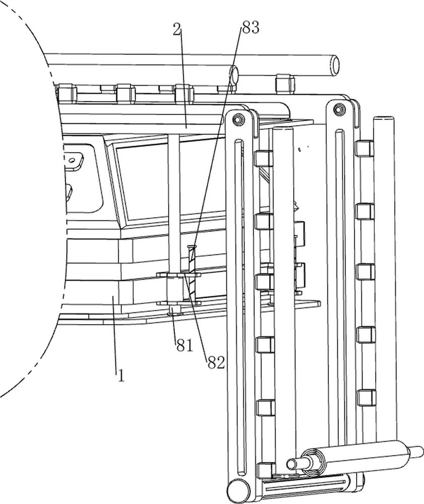
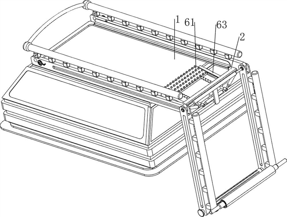
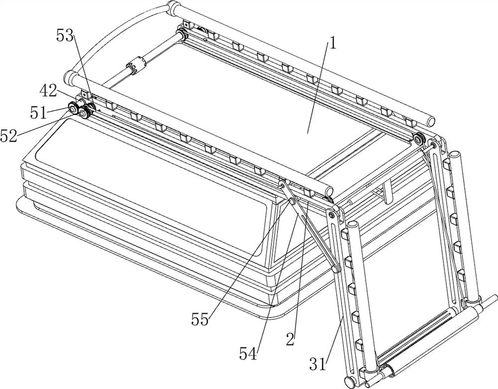
[0034] A conveying device for greening on the top of a building, such as Figure 1-10 As shown, it includes a bottom plate 2, a first slide rail 3, a second slide rail 31, a sliding sleeve 32, a roller 33, a conveying mechanism 4, a rotating mechanism 5 and a blanking mechanism 6, and the bottom plate 2 is installed on the building 1 by bolts. The position of the top, the first slide rail 3 is welded on the front and back sides of the top of the bottom plate 2, the second slide rail 31 is rotatably connected between the right side of the bottom plate 2, and the right part of the second slide rail 31 is slidably connected with a sliding sleeve 32, Sliding sleeve 32 can slide on the second slide rail 31, and between two sliding sleeves 32, roller 33 is connected in a rotatable manner, and roller 33 can rotate, and the lawn can be rolled up by roller 33. A conveying mechanism 4 is provided, a rotating mechanism 5 is provided on the bottom plate 2, and the rotating mechanism 5 can...

Embodiment 2

[0040] On the basis of Example 1, such as figure 1 , figure 2 , Figure 11 and Figure 12 As shown, it also includes a clamping mechanism 7, which can clamp and limit the lawn. The clamping mechanism 7 includes a clamping plate 71, a fourth rotating shaft 72, a torsion spring 73 and a third spring 74. The fourth rotating shaft 72 is rotatably connected on the cover 32, and the fourth rotating shaft 72 is slidably connected with a clamping plate 71. The clamping plate 71 can clamp and limit the lawn. The upper and lower sides of the fourth rotating shaft 72 and the sliding A torsion spring 73 is provided between the sleeves 32 , and a third spring 74 is provided between the upper and lower sides of the left part of the clamping plate 71 and the sliding sleeve 32 .

[0041] When people roll the lawn around the roller 33, they can turn the clamping plate 71 and the fourth rotating shaft 72 outwards, so that the torsion spring 73 is twisted, and then start to roll the lawn. Af...


PUM


Abstract

The invention relates to conveying equipment, in particular to conveying equipment for building top surface greening. The invention aims to provide the conveying equipment for greening the top surface of the building, which can be used for automatically conveying and laying lawns. According to the technical scheme, the conveying equipment for building top face greening comprises a bottom plate, first sliding rails, a second sliding rail, sliding sleeves and the like, the bottom plate is installed at the top of a building through bolts, the first sliding rails are arranged on the front side and the rear side of the top of the bottom plate correspondingly, and the second sliding rail is rotationally connected between the right sides of the bottom plate; the right portion of the second sliding rail is slidably connected with the sliding sleeve. A rolling shaft rotating mode is adopted, a lawn can be wound on a rolling shaft, then a double-shaft motor works, a first pull rope drives a sliding sleeve to move, then the rolling shaft and the lawn are pulled leftwards, and therefore the effect of automatically conveying the lawn can be achieved.

Description

technical field [0001] The invention relates to a conveying device, in particular to a conveying device for greening on the top surface of a building. Background technique [0002] In order to beautify the city, the greening of various parts of the city can not only improve the aesthetics of the city, but also reduce the pollution of the exhaust gas to the air. Now some buildings also need to be greened on the top. Since the buildings are generally at a high place, so for Transporting the lawn has become a big problem, and now there are some conveying equipment to transport the lawn. [0003] The patent application number is CN202022769474.6 A construction device for greening the top surface of a building, including a delivery box, a first pulley is fixed on the bottom side of the delivery box, and a threaded rod, the middle part of the threaded rod is fixed with a rotating plate, and the bottom end of the threaded rod is fixed with an extrusion plate; the other side of the...

Claims


Application Information

Patent Timeline
IPC IPC(8): A01G20/10A01G20/18A01G25/09
CPCA01G20/10A01G20/18A01G25/09
Inventor 陈国金
Owner 陈 国金
Learn More