Swing type one-way sprinkler for agricultural planting
A swing type, sprinkler irrigation technology, applied in the directions of agriculture, application, and botany equipment and methods, can solve the problems of simple structure of sprinkler irrigation equipment, inconvenient use and operation, lack of adjustment function of sprinkler irrigation equipment, etc., and achieves compact overall structure design, Improve the efficiency of sprinkler irrigation and improve the effect of sprinkler irrigation
- Summary
- Abstract
- Description
- Claims
- Application Information
AI Technical Summary
Problems solved by technology
Method used
Image
Examples
Embodiment 1
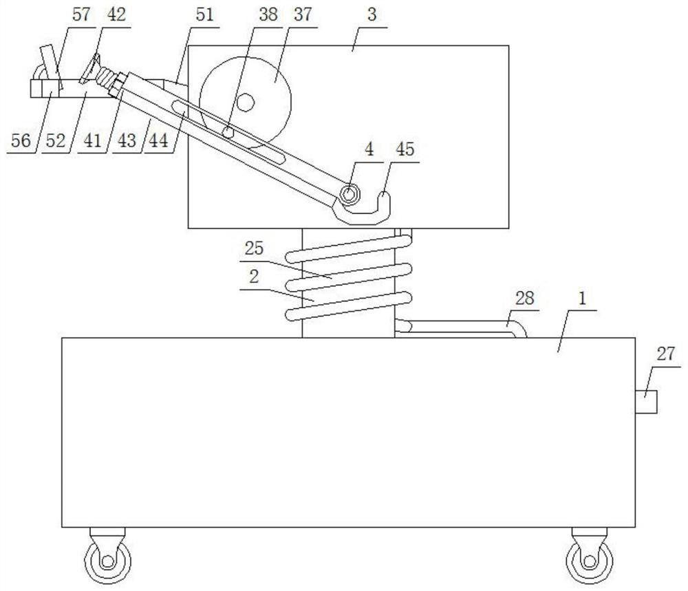
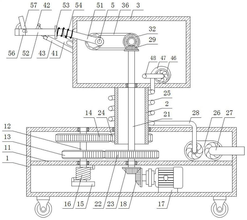
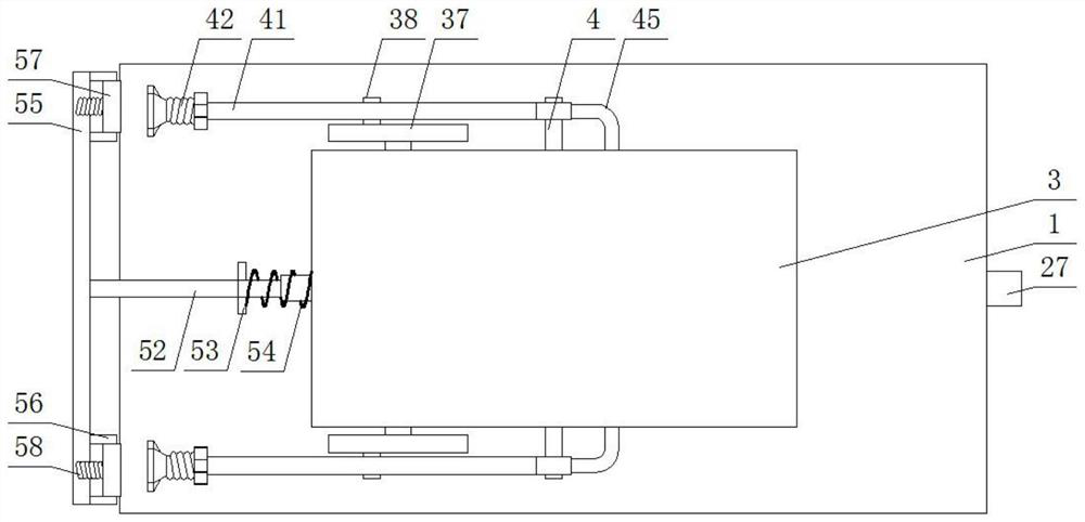
[0033] Embodiment 1: This embodiment provides a swinging one-way sprinkler for agricultural planting, see Figure 1-6 Specifically, it includes a bottom box 1 and a sprinkler irrigation box 3. The bottom box 1 is a rectangular box placed horizontally and horizontally. The four corners of the bottom surface of the bottom box 1 are provided with moving wheels. The middle part of the bottom box 1 is provided with a horizontal plate 11. , the middle part of the top surface of the bottom box 1 is provided with a circular through hole, and the inside of the circular through hole is provided with a concentric fixed bearing ring. There is a hollow tube 2 fixed vertically, the bottom end of the hollow tube 2 runs through the bearing ring and extends to the inner top of the bottom box 1, and the bottom end of the hollow tube 2 is connected with the bottom box 1 through an engaging mechanism; The concentric position is provided with the first bearing penetrating and fixed in the middle o...
Embodiment 2
[0042] Embodiment two: in embodiment one, refer to figure 2 , Figure 5 and Figure 6 , there is also the problem of how to avoid the helical tube being torn off when the sprinkler tank rotates. Therefore, on the basis of the first embodiment, the engagement mechanism of this embodiment includes a linkage shaft 12, which is located at the bottom end of the hollow cylinder 2 in the bottom box 1 A concentrically fixed gear ring 24 is set, located between the horizontal plate 11 and the hollow cylinder 2, and a concentrically fixed first gear 22 is set on the drive shaft 21. The left side of the top surface of the horizontal plate 11 and the bottom box 1 The left side of the inner top wall is provided with through and fixed linkage bearings, and the upper and lower ends of the linkage shaft 12 are respectively inserted in the corresponding linkage bearings;
[0043] At the position where the gear ring 24 is flush, the linkage shaft 12 is sleeved with a concentrically fixed sec...
Embodiment 3
[0047] Embodiment three: In embodiment one, there is also the problem that the water sprayed by the high-pressure nozzle is in a direct state, and the crops cannot be evenly sprayed and irrigated. Therefore, on the basis of embodiment one, this embodiment also includes:
[0048] In the present invention, the middle part of the reciprocating shaft 33 is provided with a coaxially connected crankshaft 5, and the top of the left side of the sprinkler box 3 is provided with a flat trapezoidal through hole, and the middle part of the crankshaft 5 is provided with a crank rod 51 connected in rotation. The outer end of the crank rod 51 runs through the trapezoidal through hole and is fixedly connected with the cross bar 52, and the inner end of the cross rod 52 is provided with a retaining ring 53, which is located between the retaining ring 53 and the sprinkler box 3 between the cross rod 52 and the crank rod. A tension spring 54 is sheathed at the joint 51;
[0049] The outer end of...
PUM
 Abstract
Description
Claims
Application Information
 - R&D
- Intellectual Property
- Life Sciences
- Materials
- Tech Scout
- Unparalleled Data Quality
- Higher Quality Content
- 60% Fewer Hallucinations
Browse by: Latest US Patents, China's latest patents, Technical Efficacy Thesaurus, Application Domain, Technology Topic, Popular Technical Reports.
© 2025 PatSnap. All rights reserved.Legal|Privacy policy|Modern Slavery Act Transparency Statement|Sitemap|About US| Contact US: help@patsnap.com


