Bone traction needle force sensing system based on FBG optical fiber

A bone traction needle and sensing system technology, applied in the field of medical devices, can solve problems such as the inability to establish a mapping relationship, the inability to establish a multi-calcaneal needle force measurement and force mapping relationship, and the six-dimensional force sensor can not respond, etc., to achieve a compact structure Effect

Pending Publication Date: 2022-04-22
HARBIN INST OF TECH
View PDF5 Cites 0 Cited by
  • Summary
  • Abstract
  • Description
  • Claims
  • Application Information

AI Technical Summary

Problems solved by technology

One is that the six-dimensional force sensor is far away from the bone tissue, so it cannot accurately represent the external force on the bone tissue: the fixed position of the six-dimensional force sensor is at the end of the surgical robot, and the end of the bone needle is connected with the end of the surgical robot, and the tip of the bone needle is fixed with the bone tissue. In this way, the position of the six-dimensional force sensor is far away from the bone tissue, and the readings of the six-dimensional force sensor cannot be used as a representation of the external force on the bone tissue, and an accurate mapping relationship cannot be established.
The second is that the six-dimensional force sensor at the end of the surgical robot cannot reflect the force relationship between each bone needle and bone tissue: usually multiple bone needles are required to sense the external force on the bone tissue at the same time during the operation, but the six-dimensional force sensor can only sense one. The external force on the spicule or the resultant force on multiple calcaneal pins cannot establish the force measurement of multiple calcaneal pins and the force mapping relationship with bone tissue

Method used


Image

  • Bone traction needle force sensing system based on FBG optical fiber
  • Bone traction needle force sensing system based on FBG optical fiber
  • Bone traction needle force sensing system based on FBG optical fiber

Examples


Embodiment 1

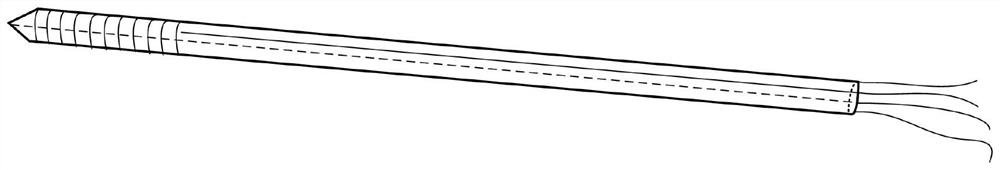
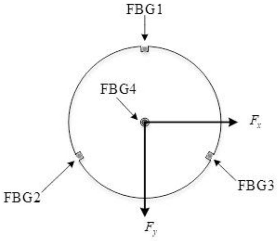
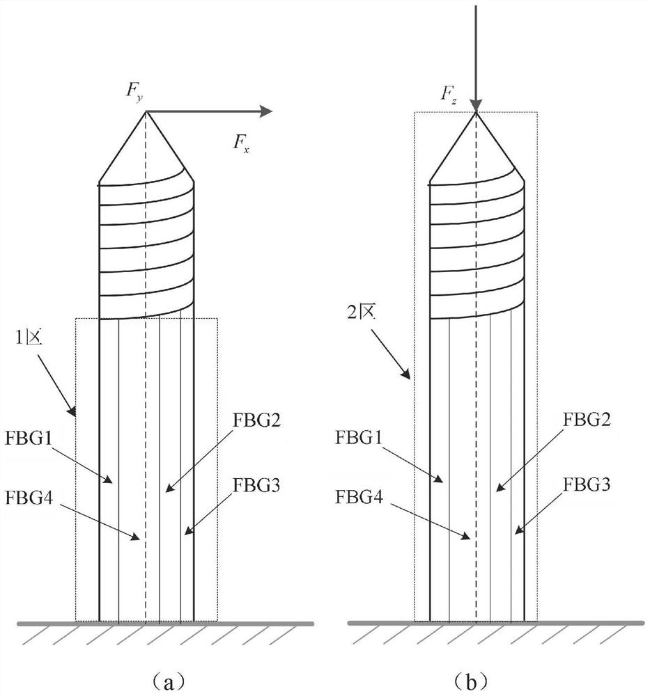
[0039] The bone traction needle force sensing system based on FBG optical fiber designed in this embodiment is as follows: figure 1 shown. First of all, the number of optical fibers needs to be determined. In theory, only three optical fibers are needed to sense the three-dimensional force on the bone needle in the surgical environment. However, fiber Bragg gratings are not only affected by strain, but also easily affected by temperature, so the design and layout of FBG The four optical fibers from fiber 1 to FBG fiber 4 sense the three-dimensional force on the bone needle; secondly, it is necessary to determine the layout of the bone needle. The three-dimensional force on the bone needle is divided into axial force and radial force, so the four optical fibers are divided into Arranged in two parts, one optical fiber (FBG optical fiber 4) is arranged on the central axis of the bone needle. This optical fiber coincides with the direction of the axial force. The next three opti...

Embodiment 2

[0077] The difference between this embodiment and Embodiment 1 is that the two-dimensional force measurement method does not arrange the central FBG optical fiber 4, and the specific method is as follows:

[0078] The strain is linearly related to the moment and thus proportional to the lateral force applied to the tip of the bone pin:

[0079]

[0080] where: ε m is the strain on the FBG optical fiber, M is the bending moment caused by the lateral force, r is the radial distance from the axis of the spicule to the FBG optical fiber on the cross section of the spicule, I is the moment of inertia, F t is the external force applied to the tip of the bone needle, and d is the axial distance from the tip of the bone needle to the FBG fiber.

[0081] The displacement of the Bragg wavelength of the FBG sensor is linearly related to the local strain and the temperature change:

[0082] Δλ=k ε ε+k ΔT ΔT (17);

[0083] Among them, Δλ is the center variation of the Bragg grating, ...


PUM


Abstract

The invention discloses a bone traction needle force sensing system based on FBG optical fibers, the bone traction needle force sensing system comprises optical fibers and a bone traction needle, and the optical fibers comprise FBG optical fibers 1-4; the FBG optical fibers 1-3 are arranged on the outer surface of the bone traction needle along the length direction of the bone traction needle; the FBG optical fiber 4 is arranged in a hollow shaft of the bone traction needle in the length direction of the bone traction needle, coincides with the central axis of the bone traction needle and is used for sensing the axial force borne by the bone traction needle. The outer surface of the bone traction needle is radially provided with three grooves at equal intervals, the included angle between every two grooves is 120 degrees, and FBG optical fibers 1-3 are arranged in the grooves and used for sensing the radial force borne by the bone traction needle. According to the method, the mapping relation between the surgical instrument deformation and the reset force is constructed, and the instrument-bone-soft tissue interaction force sensing model is established, so that unnecessary injury to a patient due to overlarge reset force in the reset operation process is avoided.

Description

technical field [0001] The invention belongs to the technical field of medical instruments, and relates to a bone traction needle force sensing system, in particular to a bone traction needle surgical instrument designed based on a fiber Bragg grating (FBG) and capable of detecting deformation. Background technique [0002] Currently, high-violence injuries, mainly pelvic fractures, are increasing. Due to the complex anatomical structure and deep position of the pelvis, and the distribution of many important blood vessels, nerves and other organs around, secondary injuries and surgical complications are very likely to occur during the reduction operation, resulting in the fatal and disability rate of unstable pelvic fractures as high as 10~ 50%. With the development of minimally invasive technology, closed reduction of pelvic fractures represented by robots plus minimally invasive screw technology can avoid intraoperative or postoperative injuries and complications caused b...

Claims


Application Information

Patent Timeline
IPC IPC(8): A61B34/30A61B17/66A61B90/00
CPCA61B34/30A61B34/70A61B34/77A61B17/66A61B90/06A61B2090/064Y02T90/00
Inventor 王伟东杜志江王韩
Owner HARBIN INST OF TECH
Why Eureka
Try Eureka