Multi-section sawing machining automatic production line
An automatic production line and sawing technology, applied in metal processing, metal sawing equipment, metal processing equipment, etc., can solve the problems of low production efficiency, sawing line speed, feed speed cannot be adjusted by frequency conversion, and multi-segment sawing cannot be performed. , to achieve the effect of improving production efficiency
- Summary
- Abstract
- Description
- Claims
- Application Information
AI Technical Summary
Problems solved by technology
Method used
Image
Examples
Embodiment 1
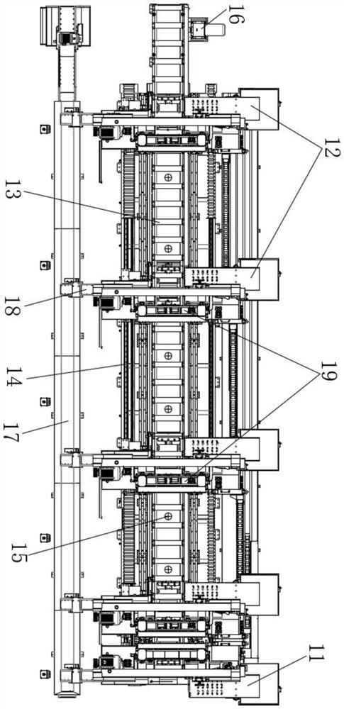
[0025] Example 1, such as figure 1 As shown, a multi-segment sawing and processing automatic production line is mainly used for cutting steel blanks such as round materials, square materials, pipes and profiles that are bundled. The sawing production line includes a cutting station 1, and the cutting station 1 is equipped with corresponding sensors where detection and correction are required.
[0026] Wherein, the cutting station 1 includes a fixed sawing group 11, a mobile sawing group 12, a feeding frame 13 and an electrical control system. Among them, the electrical control system is automatically controlled by CNC system. Both sides of the feeding frame 13 are provided with slide rails 14, and the fixed sawing group 11 is installed on one side of the feeding frame 13, which has a fixed positioning function and serves as a reference sawing surface. The mobile sawing group 12 is provided with at least one group and slides on the top conveying direction of the feeding frame...
Embodiment 2
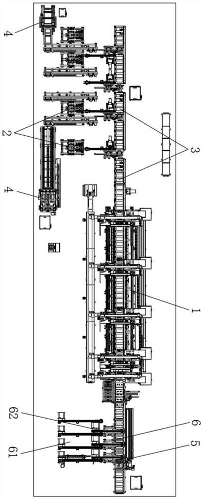
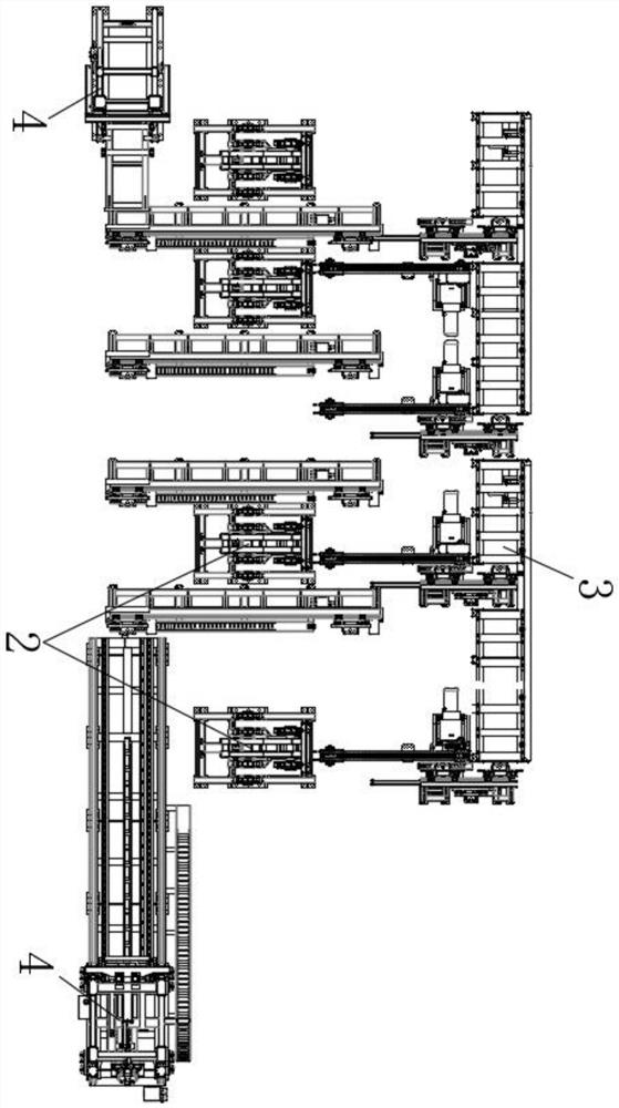
[0041] Example 2, such as figure 2 with image 3 As shown, on the basis of Embodiment 1, the feeding end of the cutting station 1 is provided with a material turning mechanism 2, which is used to turn the material at a certain angle, so that sawing will be more convenient, and the impact on the saw blade will be reduced. damage. Material turning mechanism 2 comprises drive parts such as turning plate that is certain angle, turning plate frame and cylinder, oil cylinder, motor, and the angle of turning plate can be set to 90 degrees or set to 120 degrees, so that be stuck on the material. The driving part is installed on the inner side of the conveyor, the turning frame is installed on one side of the driving part, the turning plate is hinged on the top of the turning plate frame, and the output end of the driving part is connected with the turning plate.
[0042] When the turning mechanism 2 is working, after the bales are aligned, it is controlled by the CNC system and aut...
Embodiment 3
[0046] Embodiment 3, aiming at the fact that the current sawing machine cannot align the ends of the entire bundle of incoming materials, and there is a lot of waste of materials. Such as figure 2 with image 3 As shown, on the basis of Embodiment 1 or 2, the feeding end of the cutting station 1 is also provided with an end surface alignment device 4, which is used to align the end surfaces of the materials. The end face clapping device 4 includes a rack for clapping and a rack for clapping, and the rack for racking is installed on the feed side of the conveyor, and one side of the rack for racking is connected to the rack by driving components such as cylinders, oil cylinders and motors.
[0047] After the bales are fed to the loading rack, the material is lifted by the rack through the driving parts in advance to reduce the friction between the bundling material and the feeding rack. The two ends of the stroke are respectively equipped with clapping boards, and the side of...
PUM
 Abstract
Description
Claims
Application Information
 - R&D
- Intellectual Property
- Life Sciences
- Materials
- Tech Scout
- Unparalleled Data Quality
- Higher Quality Content
- 60% Fewer Hallucinations
Browse by: Latest US Patents, China's latest patents, Technical Efficacy Thesaurus, Application Domain, Technology Topic, Popular Technical Reports.
© 2025 PatSnap. All rights reserved.Legal|Privacy policy|Modern Slavery Act Transparency Statement|Sitemap|About US| Contact US: help@patsnap.com


