
Loading force and driving energy transmission compensation device

A technology for compensating device and driving energy, applied in wheeled transmission, rider drive, transportation and packaging, etc., can solve the problems of energy loss of travel vehicles, large physical expenditure of riders, and single source of kinetic energy, etc. Low manufacturing cost, reduce physical energy consumption, and achieve the effect of compensation

Pending Publication Date: 2022-04-22
朱道刚
View PDF0 Cites 0 Cited by
  • Summary
  • Abstract
  • Description
  • Claims
  • Application Information

AI Technical Summary

Problems solved by technology

However, when existing vehicles such as bicycles and electric vehicles are in use, the source of kinetic energy driving them is relatively single, and they only rely on their own power to drive. A large amount of energy loss in travel vehicles. For example, during the riding process of a bicycle, it is only driven by the rider's own strength, which often causes the rider to have a large physical expenditure and is prone to fatigue. It is not suitable for long-distance long-distance riding. Therefore, under the same condition of energy consumption, how to prolong the traveling distance of vehicles has become an urgent problem to be solved by those skilled in the art.

Method used


Image

  • Loading force and driving energy transmission compensation device
  • Loading force and driving energy transmission compensation device
  • Loading force and driving energy transmission compensation device

Examples


Embodiment 1

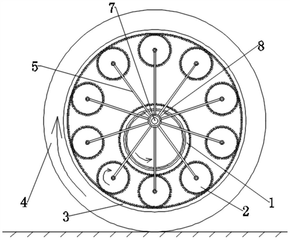
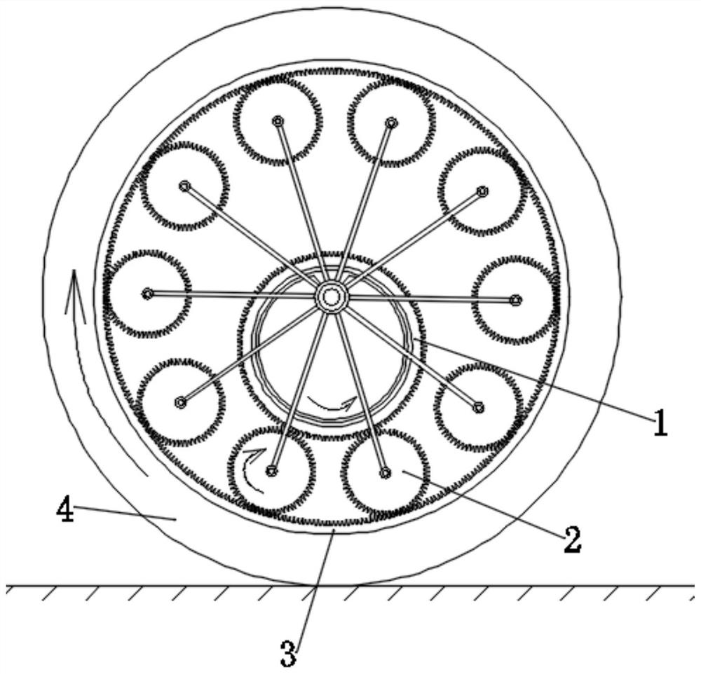
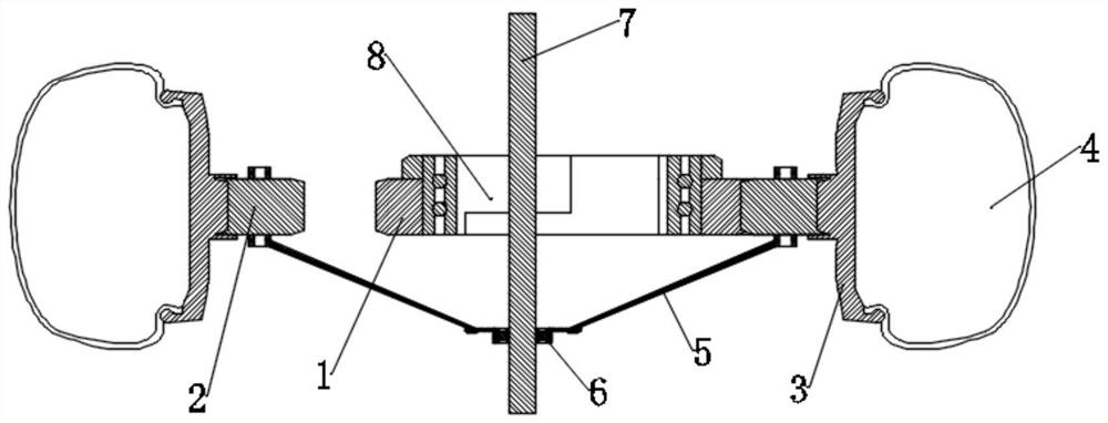
[0042] like Figure 1 to Figure 8 As shown, a load force and drive energy transmission compensation device of the present invention includes a sun gear 1, a planetary gear 2, a planetary gear ring 3 and a wheel 4, and the outer ring of the planetary gear ring 3 is matched with the wheel 4 , and the planetary gear ring 3 rotates coaxially with the wheel 4; the planetary gear 2 meshes with the inner ring of the planetary gear ring 3, and the planetary gear 2 can rotate around the planetary gear ring 3 The rotation axis revolves, and the planetary gear 2 can rotate around its own axis; when the planetary gear 2 meshes with the sun gear 1, the planetary gear 2 drives the sun gear 1 to rotate around its own axis . In this embodiment, firstly, the gear set system composed of sun gear 1 and planetary gear 2 is a follower in this embodiment; during the movement, first, the planetary gear ring 3 starts to rotate under the action of external force, and then rotates The planetary gear ...

Embodiment 2

[0058] like Figure 1 to Figure 8 As shown, the device is understood based on the relative curve action. For example, when the car body is in motion, it drives the planetary gear 2 to revolve and rotate, and the relative curve of the planetary gear 2 acts on the upper and lower edges of the planetary gear 2. A force is generated. At this time, the lower edge of the planetary wheel 2 meshes with the planetary gear ring 3. The force of the lower edge of the planetary wheel 2 can be used to overcome the load of the vehicle body movement, and the force of the upper edge of the planetary wheel 2 is used to drive The sun gear 1 rotates, and when the sun gear 2 rotates, it can be connected to an external load through the second meshing teeth 12. At this time, the energy on the sun gear 2 can be transmitted outwards and can be stored as energy by an energy storage device. The initial kinetic energy for the next movement.


PUM


Abstract

The invention discloses a loading force and driving energy transmission compensation device which comprises a sun wheel, a planet wheel, a planet wheel gear ring and a wheel, and the outer ring of the planet wheel gear ring and the wheel are matched and coaxially rotate; the planet wheel is meshed with the inner ring of the planet wheel gear ring, and the planet wheel can revolve around the rotating axis of the planet wheel gear ring and can rotate around the axis of the planet wheel; when the planet gear is meshed with the sun gear, the planet gear drives the sun gear to rotate around the axis of the sun gear. When the wheel rotates, the planet wheel meshed with the wheel can be driven to revolve around the rotating axis of the planet wheel gear ring and rotate around the axis of the planet wheel gear ring at the same time, the planet wheel can be meshed with the sun wheel when rotating to the lower position in the rotation process, and the sun wheel is driven to rotate around the axis of the sun wheel. When kinetic energy is generated, forward force can be generated to act on forward movement of the bicycle body, power compensation is carried out on the forward movement of the bicycle body, physical consumption of a rider can be effectively reduced, and therefore the technical effect of saving labor is achieved.

Description

technical field [0001] The invention relates to the technical field of vehicles, in particular to a load force and drive energy transmission compensation device. Background technique [0002] With the improvement of living standards, people choose more and more means of transportation for travel, such as bicycles, electric vehicles, automobiles, aircraft, ships and so on. However, when existing vehicles such as bicycles and electric vehicles are in use, the source of kinetic energy driving them is relatively single, and they only rely on their own power to drive. A large amount of energy loss in travel vehicles. For example, during the riding process of a bicycle, it is only driven by the rider's own strength, which often causes the rider to have a large physical expenditure and is prone to fatigue. It is not suitable for long-distance long-distance riding. Therefore, under the condition of the same energy consumption, how to prolong the traveling distance of the vehicle ha...

Claims


Application Information

Patent Timeline
Patent Type & Authority Applications(China)
IPC IPC(8): B62M1/10B62M11/02
CPCB62M1/10B62M11/02
Inventor 朱道刚朱永杰
Owner 朱道刚
Learn More