Energy-saving spiral conveying equipment

A screw conveying and equipment technology, which is applied in the field of energy-saving screw conveying equipment, can solve problems affecting automobiles, the looseness of the connection end of the head shaft and tail shaft, abnormal noise of the screw conveying equipment, etc.

Pending Publication Date: 2022-04-22
SHANDONG HUALIAN MINING
View PDF0 Cites 0 Cited by
  • Summary
  • Abstract
  • Description
  • Claims
  • Application Information

AI Technical Summary

Problems solved by technology

[0004] Aiming at the deficiencies of the prior art, the present invention provides an energy-saving screw conveying equipment, which has the advantages of head axis and tail axis limit, offset automatic correction, adjustable feeding height and surrounding discharge, which solves the problems in the background technology. The proposed material residue or accumulation inside the equipment for a long time will lead to loosening of the connection ends of the head shaft and tail shaft, causing abnormal noise in the screw conveying equipment, and because the whole equipment is connected by welding, the input cannot be adjusted when the material conveying volume is large. The height of the feed port will affect the efficiency of the conveying and the transportation of the car is moving, and the whole equipment cannot be turned during the conveying process. The car needs multiple calibrations to make the feed port discharge the material into the car hopper.

Method used


Image

  • Energy-saving spiral conveying equipment
  • Energy-saving spiral conveying equipment
  • Energy-saving spiral conveying equipment

Examples


Embodiment Construction

[0025] The following will clearly and completely describe the technical solutions in the embodiments of the present invention with reference to the accompanying drawings in the embodiments of the present invention. Obviously, the described embodiments are only some, not all, embodiments of the present invention. Based on the embodiments of the present invention, all other embodiments obtained by persons of ordinary skill in the art without making creative efforts belong to the protection scope of the present invention.

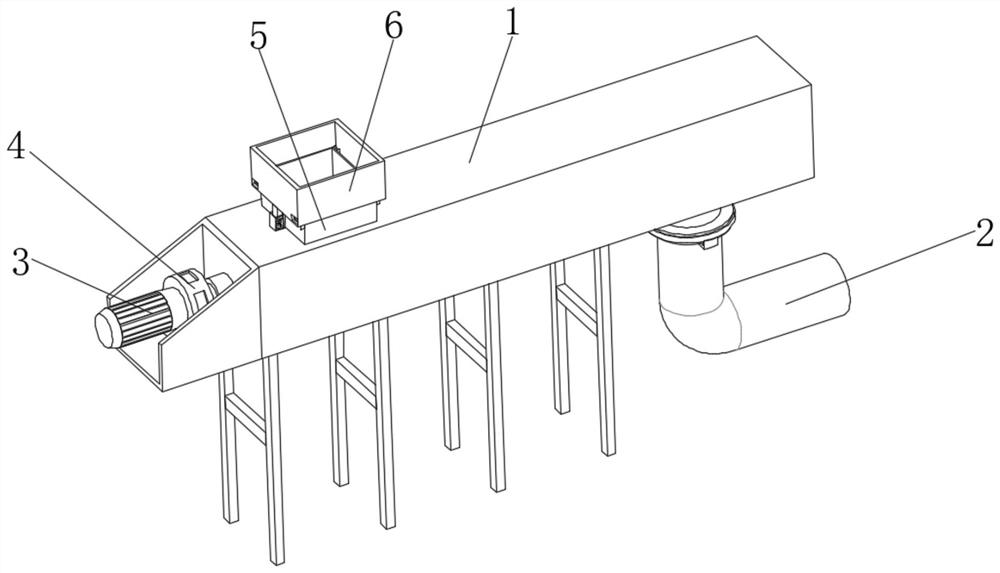
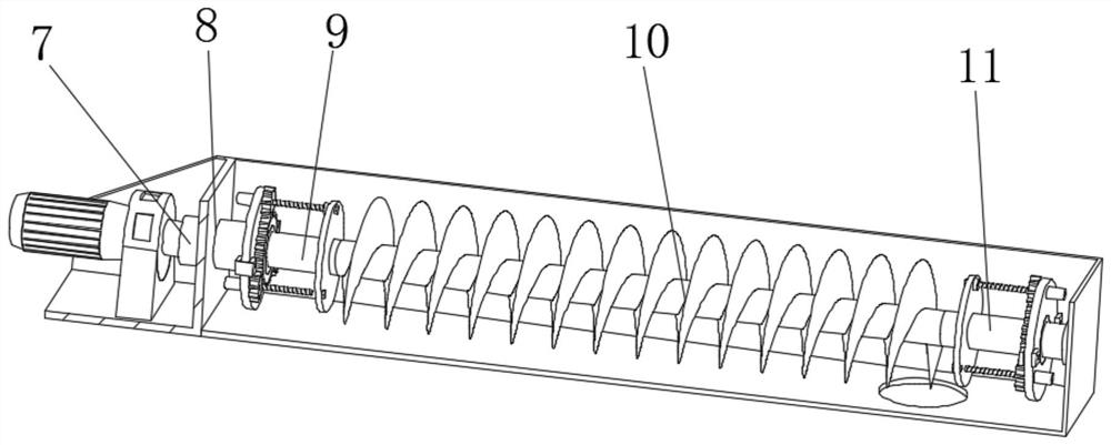
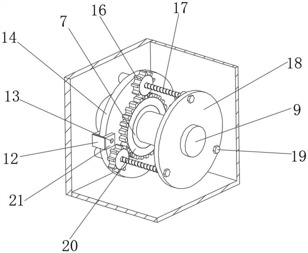
[0026] see Figure 1-7, an energy-saving screw conveying device, including a device casing 1, a connecting groove 8 is opened on one side of the inner wall of the device casing 1, a bearing seat 7 is fixedly clamped inside the connecting groove 8, and a head shaft 9 is arranged inside the bearing seat 7 , the side of the head shaft 9 is fixedly installed with a threaded blade 10, and the side of the threaded blade 10 is fixedly installed with a tail shaft 11. ...


PUM


Abstract

The invention relates to the technical field of mining equipment, and discloses energy-saving spiral conveying equipment which comprises an equipment shell, a connecting groove is formed in one side of the inner wall of the equipment shell, and a bearing seat is fixedly clamped in the connecting groove. According to the energy-saving spiral conveying equipment, a threaded rod rotates and moves leftwards in a connecting through pipe fixedly clamped in a circular groove formed in a fixed disc, so that a connecting clamping piece on the side face of the threaded rod is always attached to the surfaces of a head shaft and a tail shaft through a connecting disc fixed through a bolt, and the purpose of automatic correction is achieved; fixing discs are fixed through fixing columns in extension plates fixedly connected with fixing plates fixedly installed on the two sides in an equipment shell, and the installation heights of the fixing plates are located at the same horizontal height, so that it is guaranteed that connecting discs installed on a head shaft and a tail shaft are located at the same horizontal height; the head shaft and the tail shaft are limited by connecting clamping pieces on the side faces of the threaded rods through connecting discs fixed through bolts, and the linkage performance of the head shaft and the tail shaft which deviate in the correcting and adjusting process is guaranteed.

Description

technical field [0001] The invention relates to the technical field of mining equipment, in particular to energy-saving screw conveying equipment. Background technique [0002] In the process of mining and processing in the mining industry, it is necessary to use screw conveyor equipment to transport materials. Screw conveyor equipment is a mechanical device that uses a motor to drive a screw to rotate and push materials to achieve the purpose of transportation. It can be transported horizontally, inclined or vertically. It has a structure Simple, small cross-sectional area, good sealing, convenient operation, easy maintenance, convenient closed transportation, etc. Its working principle is that the rotating helical blade pushes the material to be transported by the screw conveyor, so that the material does not get in contact with the screw conveyor blade. The force rotating together is the weight of the material itself and the frictional resistance of the screw conveyor cas...

Claims


Application Information

Patent Timeline
Patent Type & Authority Applications(China)
IPC IPC(8): B65G33/14B65G33/26B65G33/32B65G67/04
CPCB65G33/14B65G33/265B65G33/32B65G67/04B65G2201/04
Inventor 沈兴玉张纪伟翟培用
Owner SHANDONG HUALIAN MINING
Why Eureka
Try Eureka