Immersed tube joint deformation real-time monitoring method

A technology of real-time monitoring and pipe joints, which is applied in the direction of measuring devices, instruments, and optical devices, etc., can solve problems such as large movement area, measurement environment, high requirements for station location, and positioning deviation of underwater measurement, so as to reduce safety risks , Guarantee the effect of high-precision docking

Pending Publication Date: 2022-04-22
CCCC FIRST HARBOR ENG +2
View PDF0 Cites 5 Cited by
  • Summary
  • Abstract
  • Description
  • Claims
  • Application Information

AI Technical Summary

Problems solved by technology

Therefore, during the floating, sinking and docking process of the immersed tube, if the body of the immersed tube joint has obvious irregular deformation, it will cause a large deviation in the underwater measurement and positioning, which will affect the installation accuracy of the immersed tube, which will greatly affect the construction of the immersed tube tunnel. Safety poses greater risk
[0004] Since the immersed tube joint is always in motion during the floating, sinking and installation process, the measurement object is dynamic and has a large movement area, and it is difficult to directly use the high-precision measurement reference system on land for precise deformation measurement
In addition, the immersed tube joint has a structure of "two holes and one corridor". Three water tanks W1 are arranged in the middle of the two holes to control the sinking rate and depth of the immersed tube joint. High-precision total station and level commonly used in the world, directly for high-precision deformation measurement
In addition, traditional precision engineering measurement methods are difficult to meet the above-mentioned requirements for high-precision measurement of geometric deformation of immersed tube joints
Although the precision total station and the level have high measurement accuracy, they have high requirements for the measurement environment and station location, and the measurement environment requires relatively static, and the measuring instruments must be placed in a stable position to observe the target
Moreover, GNSS measurement requires long-term continuous observation. The measurement accuracy of GNSS-RTK is generally at the centimeter level, and it is difficult to achieve millimeter-level measurement accuracy in a short time.

Method used


Image

  • Immersed tube joint deformation real-time monitoring method
  • Immersed tube joint deformation real-time monitoring method
  • Immersed tube joint deformation real-time monitoring method

Examples


Embodiment 1

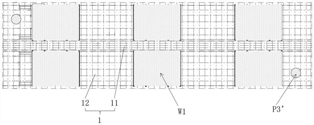
[0038] Embodiment one: if image 3Shown is the layout scheme of the visual measurement system in the middle corridor 11. The visual baseline in the middle corridor 11 is arranged at the bottom of the middle corridor 11 of the immersed tube section 1, and multiple measuring cameras 2 are installed along the length direction of the immersed tube section 1, and the multiple measuring cameras 2 constitute the visual baseline. The visual measurement line array is arranged at the cavity bottom of the middle corridor 11 of the immersed tube section 1, and a plurality of target groups 3 are installed along the length direction of the immersed tube section 1, and the multiple target groups 3 constitute a visual measurement line array.

Embodiment 2

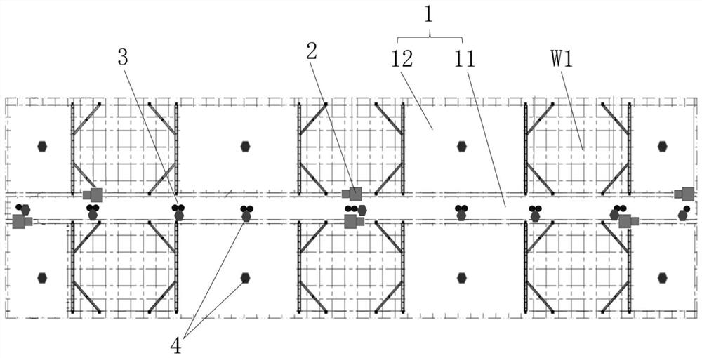
[0039] Embodiment two: if Figure 4 Shown is the layout scheme of the visual measurement system in the tunnel 12. The visual baseline in the tunnel 12 is arranged on the top of each tunnel 12 of the immersed tube section 1, and multiple measuring cameras 2 are installed along the length direction of the immersed tube section 1, and the multiple measuring cameras 2 constitute the visual baseline. The visual measurement line array is arranged on the top of each hole 12 of the immersed tube section 1, and a plurality of target groups 3 are installed along the length direction of the immersed tube section 1, and the multiple target groups 3 constitute a visual measurement line array.

Embodiment 3

[0040] Embodiment 3: Combining the visual measurement system in the middle corridor 11 of Embodiment 1 and the visual measurement system in the tunnel 12 of Embodiment 2, it is the visual measurement in the cavity of the immersed tube in Embodiment 3 System layout plan.

[0041] It can be understood that, in the above three implementations of the vision measurement system, the numbers of the measurement cameras 2 and the target groups 3 are different. The more settings of the visual measurement system, the higher the measurement accuracy will be, but the measurement cost will also increase accordingly, and the measurement cycle will become longer; therefore, those skilled in the art can according to the actual requirements and monitoring costs of real-time monitoring of the deformation of immersed tube joints, etc. Make comprehensive considerations and flexibly set up an applicable visual measurement system.

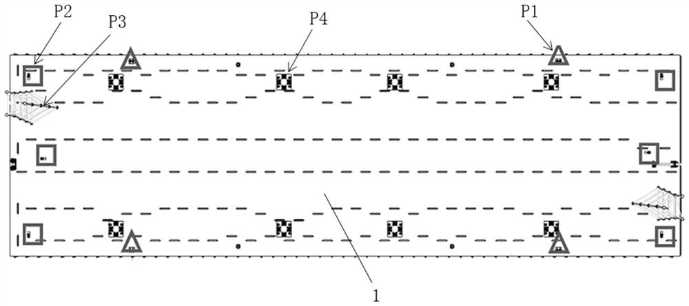
[0042] The settings of the ranging system, such as image 3 , F...


PUM


Abstract

The invention belongs to the technical field of engineering measurement, and particularly relates to an immersed tube joint deformation real-time monitoring method. The method comprises the following steps: installing a plurality of measuring cameras and a plurality of target groups at the bottom of a middle corridor and/or the top of a hole channel along the length direction of a pipe joint, and performing visual measurement on the plurality of target groups by the plurality of measuring cameras; a plurality of laser range finders are installed at the bottom of the middle gallery cavity and the bottom of the hole channel cavity in the length direction of the pipe joint, and the relative distance between the bottom of the pipe joint cavity and the top of the pipe joint cavity is measured; all measurement results are transmitted to an immersed tube measurement and control system in real time so as to obtain the results of the longitudinal relative geometric deformation of the tube joint and the change of the relative distance from the bottom of the tube joint cavity to the top of the tube joint cavity, and the results are combined with each other to carry out edge calculation so as to obtain the deformation change development condition of the immersed tube joint. According to the invention, real-time monitoring of the deformation condition of the immersed tube joint during floating transportation, immersion and installation is realized, so that the deformation change and development condition of the immersed tube joint can be accurately obtained, the field can be guided to adjust the immersion posture in time, and high-precision butt joint during immersion of the immersed tube is guaranteed.

Description

technical field [0001] The invention belongs to the technical field of engineering measurement, and in particular relates to a real-time monitoring method for the deformation of immersed pipe joints. Background technique [0002] After the immersed tube section is prefabricated in the factory, it has to go through multiple steps such as outfitting, floating, sinking and installation to complete the construction of the underwater immersed tunnel. However, during the whole process, due to the influence of seawater, wind and waves, the integrated ship and the water tank inside the tube section, the geometric shape of the immersed tube section is constantly changing. Such as figure 1 , figure 2 As shown, on the upper surface of the pipe joint, the integrated ship controls the lowering of the immersed pipe joint 1 through four cables, and controls the forward and backward movement of the pipe joint through six suspension cables. The upper and lower height control point P1 of ...

Claims


Application Information

Patent Timeline
Patent Type & Authority Applications(China)
IPC IPC(8): G01B11/16
CPCG01B11/16
Inventor 潘伟王强成益品岳远征宁进进锁旭宏孙海丰张超韩战伟董理科陶振杰朱永帅
Owner CCCC FIRST HARBOR ENG
Why Eureka
Try Eureka