Projection device
A technology of projection device and light source device, which is applied in the direction of projection device, instrument, color TV parts, etc., and can solve the problem that the depth direction of the projector is easy to increase, etc.
- Summary
- Abstract
- Description
- Claims
- Application Information
AI Technical Summary
Problems solved by technology
Method used
Image
Examples
no. 1 Embodiment approach
[0030] Next, a first embodiment of the present invention will be described with reference to the drawings.
[0031] [Outline structure of projector]
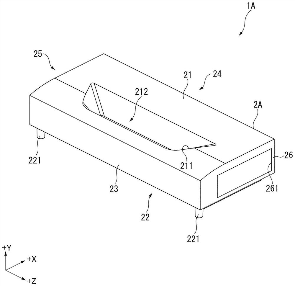
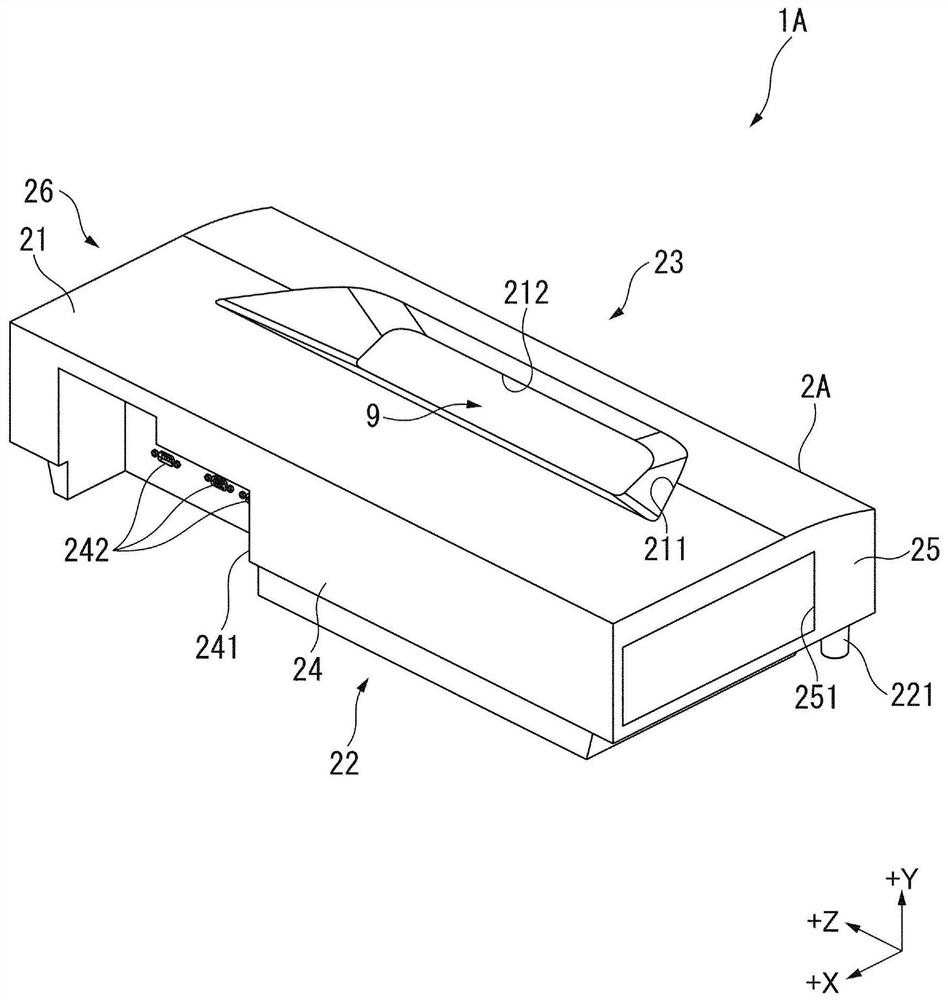
[0032] figure 1 with figure 2 It is a perspective view showing the appearance of projector 1A of this embodiment. figure 1 It is a perspective view of projector 1A viewed from the front side, figure 2 It is a perspective view of the projector 1A viewed from the rear side.
[0033] Projector 1A of the present embodiment is a projection device that modulates light emitted from a light source, generates an image corresponding to image information, and projects the generated image onto a projected surface such as a screen. Such as figure 1 with figure 2 As shown, projector 1A has exterior casing 2A.
[0034] [Structure of the exterior case]
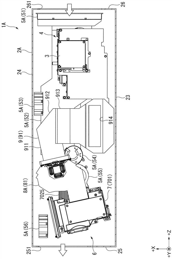
[0035] The exterior case 2A constitutes the exterior of the projector 1A, and accommodates a control device 3 , a power supply device 4 , a cooling device 5A, an image projection dev...
no. 2 Embodiment approach
[0238] Next, a second embodiment of the present invention will be described.
[0239] The projector of this embodiment has the same configuration as the projector 1A of the first embodiment, but the configuration of the image generating device is different. In addition, in the following description, the same code|symbol is attached|subjected to the part which is the same or substantially the same as what has already been demonstrated, and description is abbreviate|omitted.
[0240] Figure 11 It is a schematic diagram showing the configuration of the image projection device 6B included in the projector 1B of the present embodiment.
[0241] The projector 1B of this embodiment corresponds to a projection device. Instead of the image projection device 6, the projector 1B has Figure 11 The illustrated image projection device 6B has the same configuration and functions as those of the projector 1A of the first embodiment except for these points.
[0242] Such as Figure 11 A...
no. 3 Embodiment approach
[0258] Next, a third embodiment of the present invention will be described.
[0259] The projector of the present embodiment has the same structure as the projector 1A of the first embodiment, but the position of the inlet provided in the exterior case is different, and the structure of the cooling device is also different. In addition, in the following description, the same code|symbol is attached|subjected to the part which is the same or substantially the same as what has already been demonstrated, and description is abbreviate|omitted.
[0260] Figure 12 It is a plan view showing the internal structure of the projector 1C according to the present embodiment. in particular, Figure 12 It is a figure which looked at the internal structure of the exterior case 2C in 1 C of projectors from +Y direction. In addition, in Figure 12 In , the illustration of the heat pipe 7024 is omitted. The projector 1C of this embodiment corresponds to a projection device. Such as Figu...
PUM
 Abstract
Description
Claims
Application Information
 - R&D Engineer
- R&D Manager
- IP Professional
- Industry Leading Data Capabilities
- Powerful AI technology
- Patent DNA Extraction
Browse by: Latest US Patents, China's latest patents, Technical Efficacy Thesaurus, Application Domain, Technology Topic, Popular Technical Reports.
© 2024 PatSnap. All rights reserved.Legal|Privacy policy|Modern Slavery Act Transparency Statement|Sitemap|About US| Contact US: help@patsnap.com


