New energy ship battery drying box

A drying box, new energy technology, applied in secondary batteries, dry gas layout, battery pack components, etc., can solve the problems of desiccant soaking, battery moisture damage, loss of drying performance, etc., to avoid dumping effect

Pending Publication Date: 2022-04-22
邹长州
View PDF1 Cites 0 Cited by
  • Summary
  • Abstract
  • Description
  • Claims
  • Application Information

AI Technical Summary

Problems solved by technology

[0005] In order to overcome the disadvantages in the prior art that when water seeps into the outer box, the desiccant will be wetted by water and lose its drying performance, so that the battery will still be damaged by moisture. The purpose of the present invention is to provide a battery that can effectively avoid Damp new energy ship battery drying oven

Method used


Image

  • New energy ship battery drying box
  • New energy ship battery drying box
  • New energy ship battery drying box

Examples


Embodiment 1

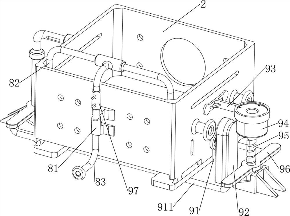
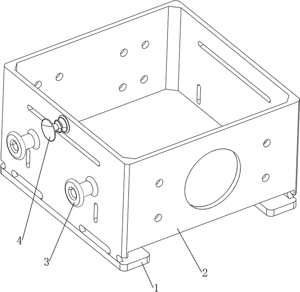
[0084] A new energy ship battery drying box, refer to Figure 1-11 , including a bottom plate 1, an outer frame body 2, a wiring pipe 3, a buzzer 4, a liquid level sensor 6, a shock absorbing mechanism 7 and a pumping mechanism 8, and the bottom of the outer frame body 2 is provided with two bottom plates 1 and two bottom plates 1 The left and right sides of the outer frame body 2 are arranged symmetrically. Two wiring tubes 3 are arranged on the left side of the outer frame body 2. The two wiring tubes 3 are arranged symmetrically front and back. The lower part of the wall is provided with a liquid level sensor 6 , the inside of the outer frame body 2 is provided with a shock absorbing mechanism 7 , and the rear side of the outer frame body 2 is provided with a pumping mechanism 8 .

[0085] refer to Figure 5 , the damping mechanism 7 includes an inner frame body 71, a limit plate 72, a first slide bar 73 and a shock absorbing spring 74, and the outer frame body 2 is slidab...

Embodiment 2

[0093] On the basis of embodiment 1, refer to Figure 12 , also includes an anti-tilt mechanism 11, the anti-tilt mechanism 11 includes a support rod 111, a second sliding sleeve 112 and an arc spring 113, the bottoms of the two special-shaped slide rails 92 are provided with a second sliding sleeve 112, and the second sliding sleeve The inside of 112 is slidably provided with a support rod 111, and two arc springs 113 are connected between each support rod 111 and the second sliding sleeve 112 on the same side.

[0094] Fix the support rod 111 on the ship, when the ship shakes, the second sliding sleeve 112 will slide on the support rod 111, and the arc spring 113 acts as a buffer, and then drives the outer frame body 2 through the slider 91 and the special-shaped slide rail 92 Swing slightly so the appliance will not tip over.

[0095] refer to Figure 13-15 , also includes a closing mechanism 12, the closing mechanism 12 includes a cover plate 121, a second mounting frame...


PUM


Abstract

The invention relates to a battery drying box, in particular to a new energy ship battery drying box. The invention provides the new energy ship battery drying box capable of effectively preventing a battery from being affected with damp. A new energy ship battery drying box comprises bottom plates and an outer frame body, the two bottom plates are arranged at the bottom of the outer frame body, and the two bottom plates are arranged in a bilateral symmetry mode; the two wiring pipes are arranged on the left side of the outer frame body, and the two wiring pipes are symmetrically arranged front and back; the buzzer used for reminding people to clean water permeating into the outer frame body in time is arranged on the upper middle portion of the left side of the outer frame body; the liquid level sensor is arranged at the middle lower part of the left wall in the outer frame body; the damping mechanism for damping the battery is arranged on the inner side of the outer frame body; and the water pumping mechanism for pumping water in the outer frame body is arranged on the rear side of the outer frame body. And when the ship vibrates, the damping springs conduct damping on the inner frame body, then damping is conducted on the battery, and therefore the effect of protecting the battery is achieved.

Description

technical field [0001] The invention relates to a battery drying box, in particular to a new energy ship battery drying box. Background technique [0002] When the existing new energy battery is installed on the ship, there is no dry sealing device. When in use, the ship is in contact with water for a long time, which makes the new energy battery easy to enter water, and eventually causes damage to the new energy battery. During the use of the ship, the ship’s The shaking is relatively large, which will drive the new energy battery to shake together, which is likely to cause damage to the battery. [0003] The patent with the publication number CN109114904A discloses a battery drying box for new energy ships, which includes an outer box and an inner box. The upper surface of the outer box is connected with an outer box cover through a rotating shaft; The first handle is connected; the inner bottom of the outer box is fixedly connected with two first electric push rods; the ...

Claims


Application Information

Patent Timeline
Patent Type & Authority Applications(China)
IPC IPC(8): H01M50/24H01M50/242H01M10/48F26B21/00
CPCH01M50/242H01M50/24H01M10/48F26B21/004F26B21/003Y02E60/10
Inventor 邹长州
Owner 邹长州
Why Eureka
Try Eureka