Three-level ANPC circuit and converter

A three-level, circuit technology, applied in the field of converters, can solve the problems of large loss of the outer tube, low utilization rate of the inner tube, and waste of cost.

Pending Publication Date: 2022-04-22
SHENZHEN HOPEWIND ELECTRIC CO LTD
View PDF0 Cites 0 Cited by
  • Summary
  • Abstract
  • Description
  • Claims
  • Application Information

AI Technical Summary

Problems solved by technology

[0003] The control methods of the three-level circuit mainly include carrier-based SPWM or space vector control (SVM). Based on these two methods, the three-level converter can be controlled to output the desired voltage, but when the traditional SPWM method or SVM method directly When applied to a three-level ANPC circuit, when the selection of switching devices in the three-level ANPC circuit is the same, there is a problem that the loss of the outer tube is greater than the loss of the inner tube, causing the junction temperature of the outer tube to be higher than the junction temperature of the inner tube, and the outer tube Limit the output capacity and life of the three-level module, and at the same time, the utilization rate of the inner tube is low, resulting in waste of cost

Method used


Image

  • Three-level ANPC circuit and converter
  • Three-level ANPC circuit and converter
  • Three-level ANPC circuit and converter

Examples


Embodiment 1

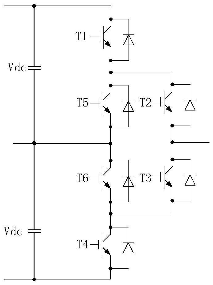
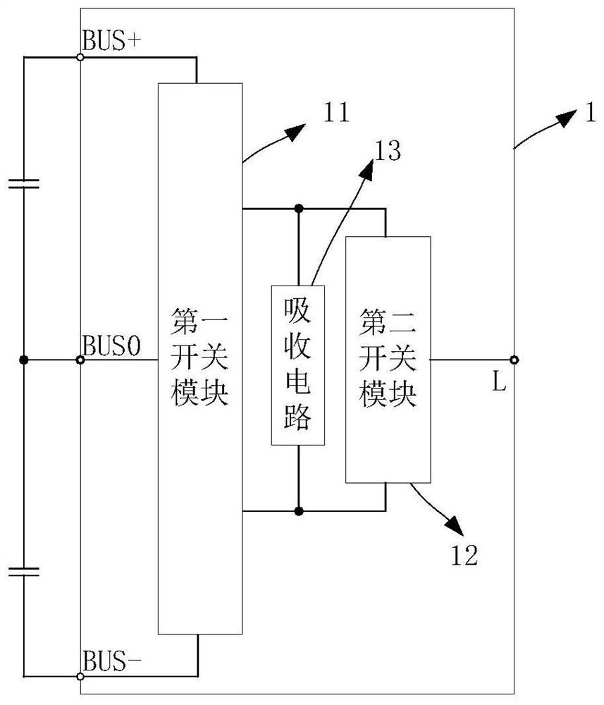
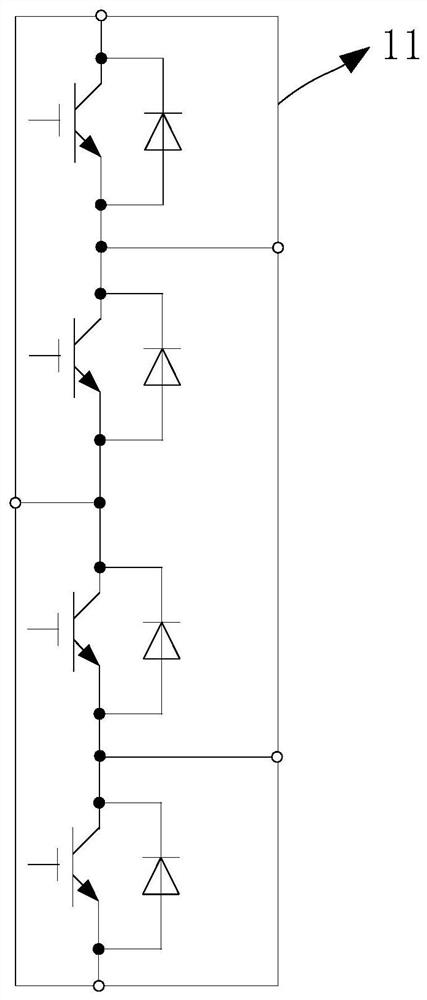
[0033] see Figure 2 to Figure 4 , figure 2 It is the overall circuit diagram of the three-level ANPC circuit of the present invention, image 3 It is the circuit diagram of the first switch module of the three-level ANPC circuit of the present invention, Figure 4 It is a circuit diagram of the second switch module of the three-level ANPC circuit of the present invention;

[0034] This embodiment discloses a three-level ANPC circuit 1, including a first switch module 11, a second switch module 12, a DC input terminal connected to the first switch module 11 and an AC input terminal connected to the second switch module 12. output terminal;

[0035] The first switch module 11 includes at least four connection ports, and the second switch module 12 includes at least two connection ports;

[0036] The three connection ports of the first switch module 11 are connected to the three potential ports of the DC input end, and the connection ports of the second switch module 12 ar...

Embodiment 2

[0044] This embodiment is based on the first embodiment, except that the first switch module 11 is composed of N thyristors connected in series, and the second switch module 12 is composed of a double-transistor IGBT.

[0045] Among them, N≥2.

Embodiment 3

[0047] In this embodiment, on the basis of Embodiment 1, the three-level ANPC circuit further includes a snubber circuit 13 for suppressing the turn-off voltage spike of the switching device, and the connection end of the second switch module 12 is connected to the snubber circuit 13, and the absorbing circuit 13 includes a absorbing capacitor and a absorbing resistor.


PUM


Abstract

The invention discloses a three-level ANPC circuit which comprises a first switch module, a second switch module, a direct current input end and an alternating current output end. The first switch module comprises at least four connecting ports, and the second switch module comprises at least two connecting ports; three connecting ports of the first switch module are connected with three potential ports of a direct current input end, and a connecting port of the second switch module is connected with the connecting port of the first switch module and an alternating current output end; the first switch module is formed by connecting N double-tube IGBTs (Insulated Gate Bipolar Transistors) in series, or is formed by connecting N thyristors in series; the second switch module is formed by connecting M double-tube IGBTs in parallel or is formed by one double-tube IGBT, N is larger than or equal to 2, and M is larger than or equal to 2. The three-level ANPC circuit can improve the utilization rate of the outer tube and the inner tube to the maximum extent, reduce the cost of the converter and balance the service life of the inner tube and the outer tube at the same time.

Description

technical field [0001] The present application relates to the technical field of converters, in particular to a three-level circuit and a converter. Background technique [0002] Three-level ANPC circuits are widely used in wind power, transmission, photovoltaic and other fields. Three-level ANPC circuits such as figure 1 As shown, it contains six switching devices T1~T6, among which T1 and T4 are the outer tubes of the ANPC circuit, T2 and T3 are the inner tubes of the ANPC circuit, and T5 and T6 are the clamping tubes of the ANPC circuit, which are applied to the three-level circuit The switching devices mainly include: Insulated Gate Bipolar Transistor (IGBT), Integrated Gate Commutated Thyristor (IGCT), Thyristor (GTO). [0003] The control methods of the three-level circuit mainly include carrier-based SPWM or space vector control (SVM). Based on these two methods, the three-level converter can be controlled to output the desired voltage, but when the traditional SPWM ...

Claims


Application Information

Patent Timeline
Patent Type & Authority Applications(China)
IPC IPC(8): H02M7/483
CPCH02M7/483
Inventor 许亚明周党生王武华王琰姜圳
Owner SHENZHEN HOPEWIND ELECTRIC CO LTD
Why Eureka
Try Eureka