Wart freezing cutting device for dermatology department

A cutting device and dermatological technology, applied in the field of medical devices, can solve the problem of no wart freezing and peeling, and achieve the effect of clear design, quick freezing and cutting, and avoiding volatilization and waste

Inactive Publication Date: 2022-04-26
焦作市第二人民医院
View PDF0 Cites 0 Cited by
  • Summary
  • Abstract
  • Description
  • Claims
  • Application Information

AI Technical Summary

Problems solved by technology

[0009] In view of the above situation, in order to overcome the defects of the prior art, the present invention provides a wart cryocutting device for dermatology, which effectively solves the problem that there is no special device integrating wart freezing and peeling at present, and it can only be cut with the help of different devices. The problem of freezing and then cutting and peeling

Method used


Image

  • Wart freezing cutting device for dermatology department
  • Wart freezing cutting device for dermatology department
  • Wart freezing cutting device for dermatology department

Examples


Embodiment 1

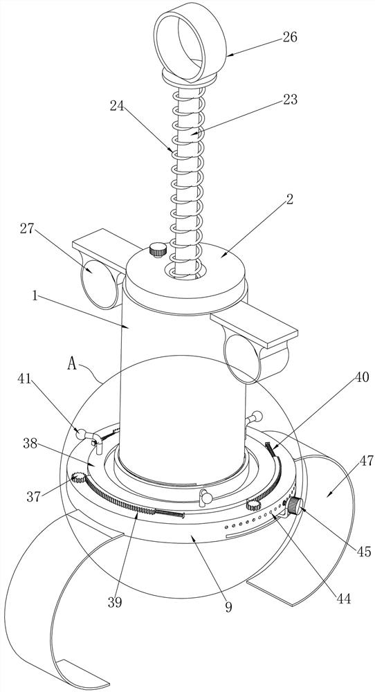
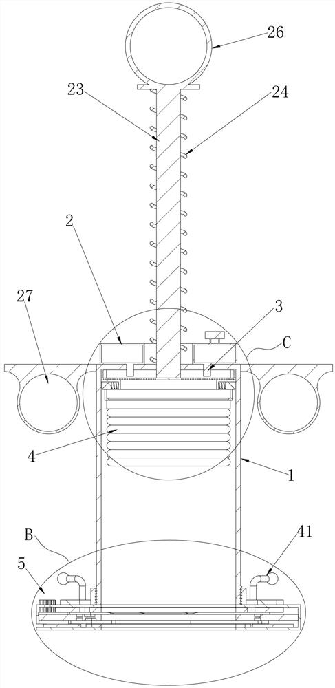
[0043]Embodiment 1, the present invention is a wart cryocutting device for dermatology, which includes a cylinder 1 with an inner hollow and an open bottom. The material of the cylinder 1 can be made of stainless steel, and a cotton cloth layer can be wrapped outside the cylinder 1. During operation, the cotton cloth layer can be held by hand. The top of the cylinder body 1 is fixedly equipped with a ring-shaped and internally hollow liquid nitrogen ring 2. The top of the liquid nitrogen ring 2 is equipped with a liquid inlet, which can be imagined as a liquid nitrogen ring. 2. Liquid nitrogen is injected into the interior for storage. The bottom of the liquid nitrogen ring 2 is connected with a push valve 3 that runs through the top of the cylinder 1 and is located inside the cylinder 1. The push valve 3 is located in the cylinder 1 and can be activated by pressing the push valve Liquid nitrogen flows into the cylinder body 1, and a freezing device 4 is installed sliding up an...

Embodiment 2

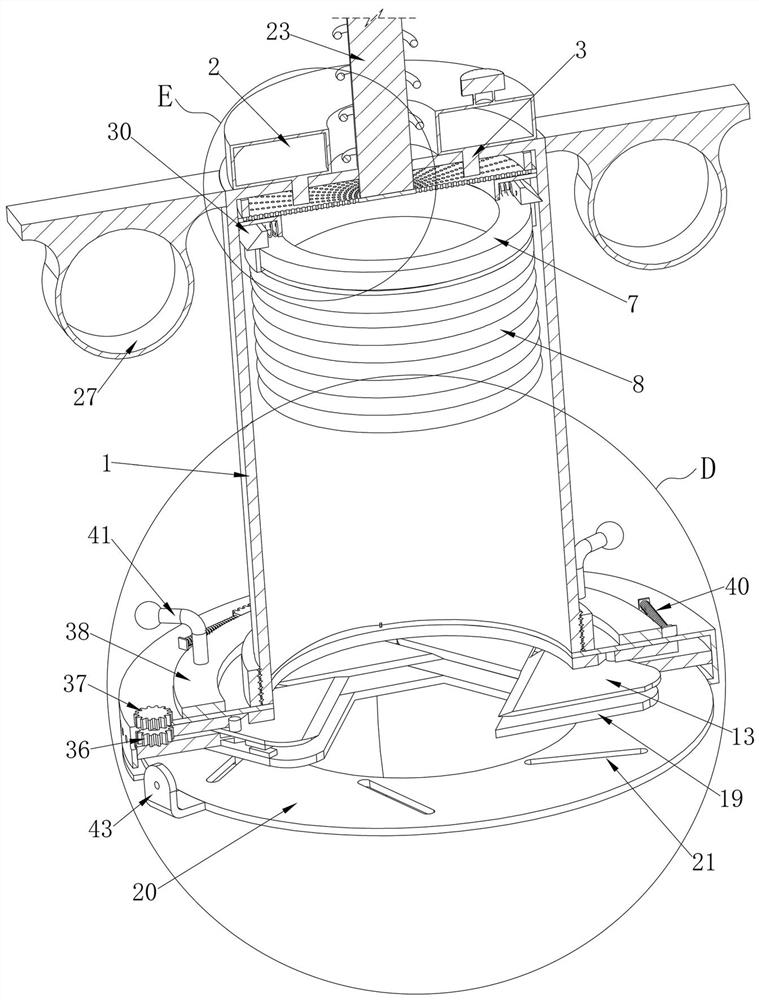
[0046] Embodiment two, on the basis of embodiment one, as attached Figure 11 As shown, the bottom surface of the chute ring 10 is provided with a clamping chute 17 corresponding to the position and shape of a plurality of cutting chute 11, each of the clamping chute 17 is slidably installed with a clip Hold sliders 18, the bottom of each of the clamp sliders 18 is fixedly connected with a clamping plate 19 that is triangular and one of its sides faces the axis of the cutting ring 9, and the initial positions of a plurality of clamping plates 19 are Located inside the cutting ring 9, and below the plurality of cutting blades 13, and close to the bottom of the cutting ring 9, when a plurality of clamping sliders 18 slide in the clamping chute 17 at the same time, they can drive a plurality of clamping plates 19 moves to the axial center of cutting ring 9 at the same time, the space between the sides of a plurality of clamping plates 19 becomes smaller gradually, thereby can cla...

Embodiment 3

[0048] Embodiment 3, on the basis of Embodiment 1, the top of the pressing screen 6 is coaxially fixedly connected with a pressing rod 23 that runs through the top of the cylinder 1, and the pressing rod 23 can drive the pressing screen 6 inside the cylinder 1 Moving up and down, the pressing rod 23 is covered with a pressing spring 24 between the top and the top of the cylinder 1. When the pressing rod 23 moves to the inside of the cylinder 1, the pressing spring 24 can be compressed. Under the effect of upward reset, the top edge of the pressing net plate 6 is fixedly connected with a rubber ring 25. When the pressing net plate 6 is in the initial position, the top of the rubber ring 25 is close to the top of the cylinder body 1. At this time, the pressing net plate 6 is not in contact with the pressing valve 3. When the sponge 8 needs to absorb liquid nitrogen, the pressing rod 23 can be lifted upwards, so that when the pressing net plate 6 moves upward, the rubber ring 25 a...


PUM


Abstract

The invention provides a wart freezing and cutting device for the dermatology department. The wart freezing and cutting device solves the problem that no special instrument integrating wart freezing and stripping exists at present. Comprising a barrel, a liquid nitrogen ring is fixed to the top of the barrel, a pressing valve located in the barrel is connected to the bottom of the liquid nitrogen ring, a freezing device slides in the barrel, and a cutting device is connected to the bottom end of the barrel; the cutting device comprises a cutting ring connected to the bottom end of the barrel, an inclined groove ring is coaxially fixed in the cutting ring, a plurality of cutting inclined grooves are formed in the top face of the inclined groove ring, cutting sliding blocks are arranged in the cutting inclined grooves in a sliding mode, cutting blades are fixed to the tops of the cutting sliding blocks, and a cutting driving ring located above the multiple cutting blades is coaxially arranged in the cutting ring in a rotating mode. And a plurality of cutting driving chutes which are distributed circumferentially penetrate through the cutting driving ring, and the top of each cutting blade is fixedly connected with a cutting driving pin which is located in one cutting driving chute. According to the wart cutting device, the multiple cutting blades located above the clamping plates are opened and closed, so that the roots of warts are cut.

Description

technical field [0001] The invention relates to the technical field of medical devices, in particular to a wart cryocutting device for dermatology. Background technique [0002] Wart (verrucae, warts) is a common chronic viral skin disease, clinically manifested as wart-like proliferation, contagious, common clinical warts mainly include common warts (verruca vulgaris), plantar warts (verruca plantaris) ) and flat warts (verruca plana), molluscum refers to molluscum contagiosum (molluscum contagiosum), which belongs to bean virus, and there are many treatment methods for warts and molluscum. In addition to drug treatment, physical therapy can generally be used, such as freezing, Curettage, peeling, electrocautery, and CO2 laser treatment are all commonly used clinical treatment methods, among which freezing and peeling are the most widely used. [0003] However, at present there is no special device for freezing and peeling warts. We can only use different devices to freeze...

Claims


Application Information

Patent Timeline
Patent Type & Authority Applications(China)
IPC IPC(8): A61B18/02
CPCA61B18/02A61B18/0218A61B2018/0225
Inventor 王坤姜云平席丽红甄希汤淑芬张方
Owner 焦作市第二人民医院
Why Eureka
Try Eureka