Special instrument for removing plaster mold after orthopedic treatment

A post-treatment, plaster cast technology, applied in the field of orthopedic equipment, can solve the problems of reducing the efficiency of plaster removal, increasing the operation intensity of medical staff, etc., to achieve the effect of improving efficiency and reducing operation intensity

Inactive Publication Date: 2022-04-26
河南科技大学第二附属医院(洛阳市第四人民医院)
View PDF0 Cites 0 Cited by
  • Summary
  • Abstract
  • Description
  • Claims
  • Application Information

AI Technical Summary

Problems solved by technology

[0004] It can be seen that clinically, medical staff use a wide variety of instruments, and during the removal process, medical staff need to frequently replace the instruments on their hands, which will increase the operating intensity of medical staff and reduce the efficiency of plaster removal

Method used


Image

  • Special instrument for removing plaster mold after orthopedic treatment
  • Special instrument for removing plaster mold after orthopedic treatment
  • Special instrument for removing plaster mold after orthopedic treatment

Examples


Embodiment 1

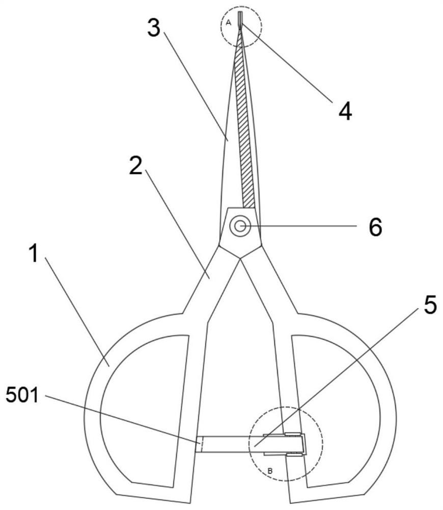
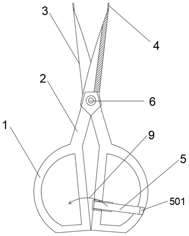
[0037] A special instrument for removing a plaster cast after orthopedic treatment, comprising a first scissors body and a second scissors body hinged to each other, each of the first scissors body and the second scissors body includes a blade part 3, a handle part 2 and a handle part 1 , the handles 2 of the first scissors body and the second scissors body are hinged by the pin 6, so that the handle 1 drives the first scissors body and the second scissors body to rotate crosswise around the pin 6.

[0038] When the handles 1 of the first scissors body and the second scissors body are in contact, the blades 3 of the two are in a crossing state, that is, the two backs of the blades are located between the two cutting edges, and the cutting edges of the two are in a state away from each other. When the handles 1 of the first scissors body and the second scissors body are in contact, the spreading function is realized; when the handles 1 of the first scissors body and the second s...

Embodiment 2

[0048] The main difference from Embodiment 1 is that the limit adjustment mechanism may include a first limit rod and a second limit rod that are correspondingly rotated on the first scissor body and the second scissor body handle 1, and the second limit rod The first limiting rod and the second limiting rod are located on the same side, and the first limiting rod and the second limiting rod are rotatably arranged on the handle part 1 , and the specific rotation setting method can refer to Embodiment 1. When the first stop bar and the second stop bar rotate until their ends touch, the blades 3 of the first scissors body and the second scissors body are in a superimposed state, and the two cutting edges are located between the two backs .

Embodiment 3

[0050] Such as Figure 9-10 As shown, the main difference from Embodiments 1 and 2 is that the limit adjustment mechanism is different, and the limit adjustment mechanism may include a buckling plate 7 and a buckling slot 8 for buckling. The inner side of the handle part 1 of the first scissors body is fixed with a limited rotating shaft through a bearing seat, and one end of the fastening plate 7 is rotationally connected with the rotating shaft. The limit shaft can use a one-word damping shaft. In addition, according to actual needs, the fastening plate 7 only needs to be rotated by 90°, so the one-word damping shaft can be a one-word damping shaft with a 90° limit. The rotation angle range of the shaft within 90°. The fastening plate 7 has an L-shaped structure, and the fastening groove 8 is correspondingly opened on the handle portion 1 of the first scissors body, on the same side as the fastening plate 7 . The short side of the fastening plate 7 is used for inserting in...


PUM


Abstract

A special instrument for removing a plaster mold after orthopedic treatment comprises a first scissor body and a second scissor body which are hinged to each other, each of the first scissor body and the second scissor body comprises a cutting edge part, a scissor handle part and a grab handle part, and the scissor handle parts of the first scissor body and the second scissor body are hinged through a pin shaft; when the grab handle parts of the first scissor body and the second scissor body are in contact, the blade parts of the first scissor body and the second scissor body are in a crossed state, the head ends of the blade parts of the first scissor body and the second scissor body are each provided with a supporting piece used for supporting gypsum, and the supporting pieces are perpendicular to the blade parts and parallel to the cutting edges of the blade parts. The operation intensity of medical staff is reduced, and the gypsum removal efficiency is improved.

Description

technical field [0001] The invention relates to the technical field of orthopedic instruments, in particular to a special instrument for removing plaster molds after orthopedic treatment. Background technique [0002] Fracture is a common bone injury disease, which is more common in children and the elderly, and also occurs in young and middle-aged people. Clinically, the use of plaster to fix the fracture end is a relatively common external fixation method after a fracture. Generally, the positions of the two joints before and after the fracture end must be fixed so that the fracture end can grow in a stable environment and the fracture is in the most connected position. good condition. After the fracture site has recovered to the standard of primary clinical healing, medical staff need to remove the plaster. [0003] When removing gypsum, cast gypsum is relatively difficult to remove. The clinical process of removing gypsum is as follows: 1. Use an electric cutting machi...

Claims


Application Information

Patent Timeline
Patent Type & Authority Applications(China)
IPC IPC(8): A61F5/05B28D1/00B28D7/00B26B13/00
CPCA61F5/05B28D1/00B28D7/00B26B13/00
Inventor 刘莹朱辉
Owner 河南科技大学第二附属医院(洛阳市第四人民医院)
Why Eureka
Try Eureka