
Massage mechanism for seat backrest

A seat back and backrest technology, which is applied to kneading massage appliances, massage auxiliary products, physical therapy, etc., can solve the problem of difficulty in ensuring the comfort and safety of car seats, threats to user safety, and difficulty in layout, etc. problem, to achieve the effect of small occupied volume, simple structure and good use effect

Pending Publication Date: 2022-04-26
NOBO AUTOMOTIVE SYST CO LTD
View PDF0 Cites 0 Cited by
  • Summary
  • Abstract
  • Description
  • Claims
  • Application Information

AI Technical Summary

Problems solved by technology

[0003] At present, professional massage chairs on the market are better than car seat back air bag (or mechanical) massage in terms of massage mode and intensity. It is difficult to ensure the comfort and safety of car seats
In addition, during the use of the existing seat back massage mechanism, the massage head cannot retreat in the face of a vehicle collision, which poses a greater threat to the safety of users

Method used


Image

  • Massage mechanism for seat backrest
  • Massage mechanism for seat backrest
  • Massage mechanism for seat backrest

Examples


Embodiment Construction

[0047] It should be noted that, in the case of no conflict, the embodiments of the present invention and the features in the embodiments can be combined with each other.

[0048] In the description of the present invention, it should be noted that if there are terms such as "upper", "lower", "inner", "outer" indicating orientation or positional relationship, it is based on the orientation or positional relationship shown in the accompanying drawings , is only for the convenience of describing the present invention and simplifying the description, but does not indicate or imply that the referred device or element must have a specific orientation, be constructed and operated in a specific orientation, and thus should not be construed as limiting the present invention. In addition, if terms such as "first" and "second" appear, they are used for descriptive purposes only, and cannot be understood as indicating or implying relative importance.

[0049] In addition, in the descripti...


PUM


Abstract

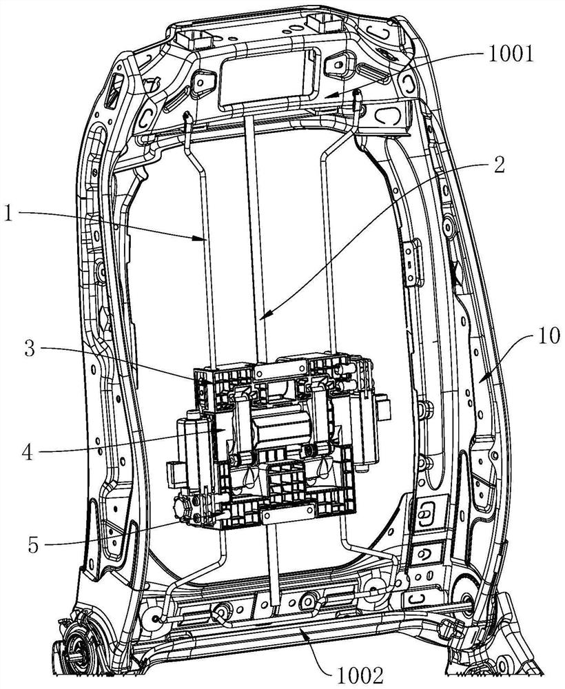
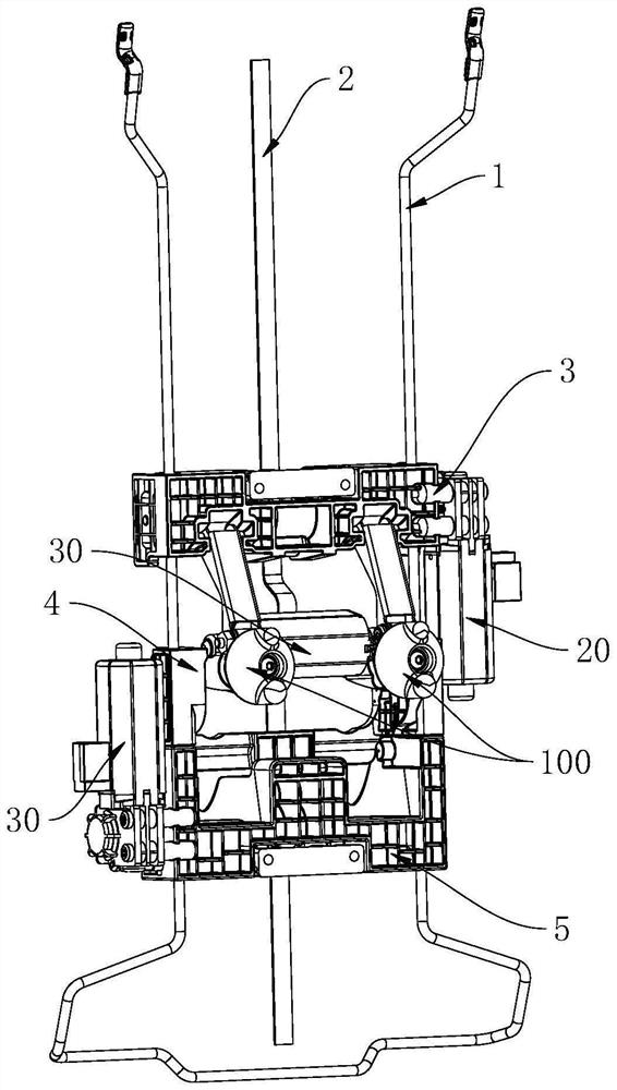
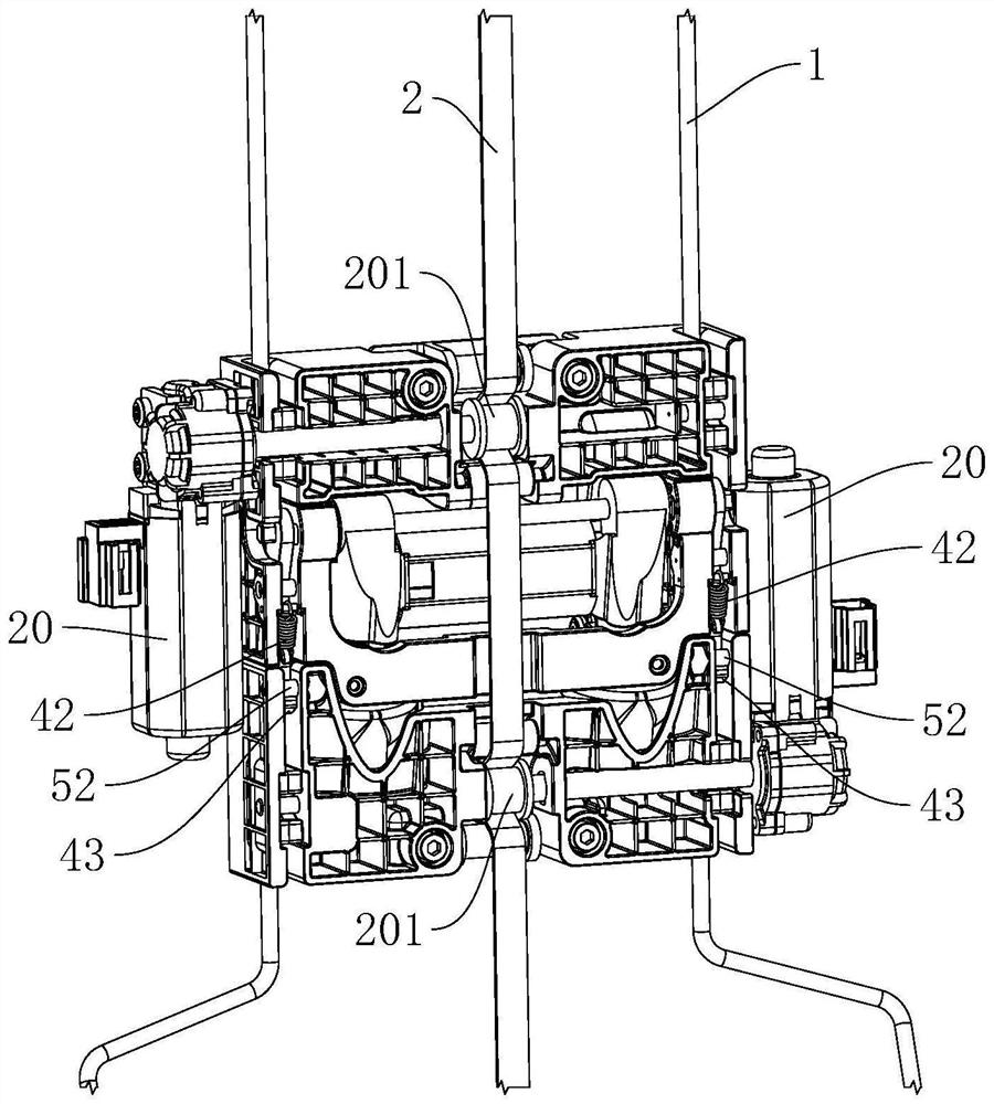
The invention provides a seat backrest massage mechanism which comprises a sliding base arranged on a backrest framework, a first sliding assembly, a second sliding assembly and a third sliding assembly, the first sliding assembly, the second sliding assembly and the third sliding assembly are sequentially arranged on the sliding base in a sliding mode, and a first driving assembly is arranged between the first sliding assembly and the sliding base. A second driving assembly is arranged between the third sliding assembly and the sliding base, a massage assembly with a massage head is hinged in the second sliding assembly, a linkage assembly is hinged between the first sliding assembly and the massage assembly, a connecting assembly is arranged between the second sliding assembly and the third sliding assembly, and when the first sliding assembly or the third sliding assembly slides, the linkage assembly is hinged to the massage assembly. When the third sliding assembly slides, the linkage assembly can drive the massage assembly to turn over, and when the third sliding assembly slides, the connecting assembly can drive the second sliding assembly to slide synchronously. According to the seat backrest massage mechanism, the massage head can be turned over by different heights and can also move along the sliding base, so that massage in various modes can be realized, and the seat backrest massage mechanism has a better use effect.

Description

technical field [0001] The invention relates to the technical field of vehicle seats, in particular to a seat back massage mechanism. Background technique [0002] At present, there are two main forms of car seat back massage: air bag massage and mechanical massage. Among them, the air bag massage is based on the air pump and the air valve electronic control module. According to the sequence control logic set by the program on the air valve electronic control module, the air pump presses the ambient air along the trachea with a certain pressure into the foam fixed on the back of the car seat. Among the several air bags on side A (the side where the car seat foam is in contact with the skin) or side B (the side where the car seat foam is in contact with the frame), the air bag is bulging and falling to achieve a pneumatic pressing massage effect. Mechanical massage is to use the electric transmission mechanism installed on the backrest frame of the car to squeeze the foam B ...

Claims


Application Information

Patent Timeline
IPC IPC(8): A61H7/00
CPCA61H7/007A61H2201/0149A61H2201/1664
Inventor 周安明熊丁张立禹孙继国
Owner NOBO AUTOMOTIVE SYST CO LTD
Learn More