
Centrifugal gas multi-stage filtering device

A stage filtration and centrifugal technology, which is applied in the field of centrifugal gas multi-stage filtration devices, can solve the problems of reduced performance, equipment breakdown, dust stickiness, etc., and achieve the effects of improving performance, prolonging service life and preventing dust accumulation

Pending Publication Date: 2022-04-26
王桥桥
View PDF12 Cites 0 Cited by
  • Summary
  • Abstract
  • Description
  • Claims
  • Application Information

AI Technical Summary

Problems solved by technology

[0005] Aiming at the deficiencies of the prior art, the present invention provides a centrifugal gas multi-stage filter device, which solves the problem that the structure of the existing gas equipment is too simple, and it only filters through the filter screen, which has poor adaptability and is harmful to some humid gases. When there is a large amount of dust, it is easy to appear sticky dust, resulting in a large amount of dust accumulation, easy to block, and then affect the filtration efficiency. In severe cases, the entire equipment will be paralyzed, affecting the service life of the equipment and reducing the performance.

Method used


Image

  • Centrifugal gas multi-stage filtering device
  • Centrifugal gas multi-stage filtering device
  • Centrifugal gas multi-stage filtering device

Examples


Embodiment example 1

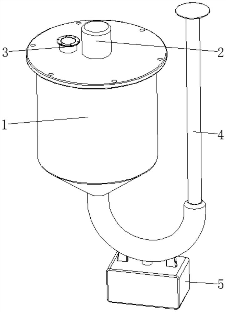
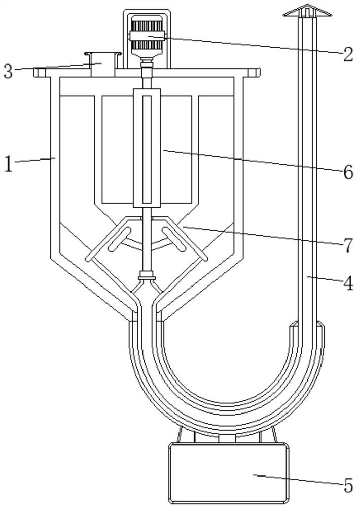
[0029] see Figure 1-6 , the present invention provides a technical solution: a centrifugal gas multi-stage filter device, including a housing 1, a driving mechanism 2, an air inlet 3, a trumpet exhaust pipe 4, and a vacuum cleaner 5, and the driving mechanism 2 is arranged on the housing 1, the air inlet 3 is set on the top of the casing 1 and close to the driving mechanism 2, the bell mouth exhaust pipe 4 is set at the bottom of the inner wall of the casing 1 and extends to the outside, and the vacuum cleaner 5 is set on the casing the bottom of body 1;

[0030] The interior of the housing 1 is provided with a stirring device 6 and a multi-stage filtering device 7. The stirring device 6 is arranged at the inner center of the housing 1 and near the top position, and the multi-stage filtering device 7 is arranged inside the housing 1, and the multi-stage filtering The device 7 is connected with the stirring device 6, and the gas is passed into the housing 1 through the air in...

Embodiment example 2

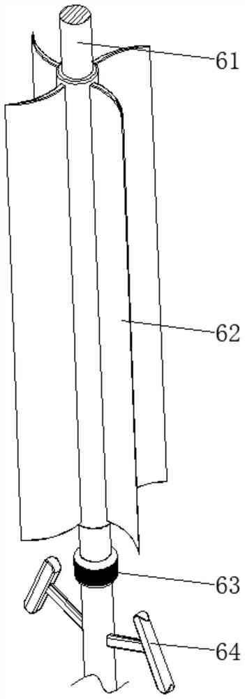
[0032] The agitating device 6 is provided with a rotating shaft 61, an arc fan blade 62, a sealing sleeve 63, and a toggle member 64. The surface top of the rotating shaft 61 is rotatably connected to the inner top of the housing 1, and the arc fan blade 62 is fixed on the surface top of the rotating shaft 61. The sealing sleeve 63 is disposed on the surface of the rotating shaft 61 and close to the bottom of the arc-shaped blade 62 , and the toggle member 64 is disposed on the bottom of the rotating shaft 61 and close to the sealing sleeve 63 .

[0033] The multi-stage filtering device 7 is provided with a conical secondary filter screen 71, a primary filter plate device 72, and an elastic knocking device 73. The inner wall of the conical secondary filter screen 71 is fixedly connected with the end of the bell mouth exhaust pipe 4, and the primary filter The plate device 72 is arranged between the two sides corresponding to the surface of the conical secondary filter screen 71...

Embodiment example 3

[0035]The primary filter plate device 72 is provided with a filter plate 721, a first rubber strip 722, and a second rubber strip 723. The filter plate 721 is arranged inside the housing 1 and is close to the conical secondary filter screen 71. The first rubber strip 722 Set on the edge of the surface of the filter plate 721 and fixedly connected with the inner wall of the housing 1, the second rubber strip 723 is set at the bottom of the filter plate 721 and fixedly connected with the surface of the conical secondary screen 71, when the conical secondary When the primary filter screen 71 is hit and vibrates, the flexibility of the first rubber strip 722 and the second rubber strip 723 is used, and the filter plate 721 will shake continuously at this time, which is convenient for particle dust to fall off. The effect, but also achieved the purpose of self-cleaning.


PUM


Abstract

The invention discloses a centrifugal gas multi-stage filtering device which comprises a shell, a driving mechanism, a gas inlet, a horn mouth exhaust pipe and a dust collector, the driving mechanism is arranged in the center of the top of the shell, and the gas inlet is formed in the position, close to the driving mechanism, of the top of the shell; the horn mouth exhaust pipe is arranged at the bottom of the inner wall of the shell and extends to the outside of the shell, the dust collector is arranged at the bottom of the shell, the stirring device is arranged in the center of the interior of the shell and is close to the top, the multi-stage filtering device is arranged in the shell, and the multi-stage filtering device is connected with the stirring device in a matched mode. The invention relates to the technical field of gas filtering equipment. According to the centrifugal gas multi-stage filtering device, the anti-blocking effect is achieved, dust in gas is rapidly filtered through centrifugal force in combination with multi-stage filtering, meanwhile, dust accumulation is effectively prevented, blocking is not prone to occurring, the filtering effect is good, and the use performance is improved.

Description

technical field [0001] The invention relates to the technical field of gas filtering equipment, in particular to a centrifugal gas multistage filtering device. Background technique [0002] With the continuous development of science and technology and the continuous progress of society, the industry has also developed rapidly. Various industrial preparation factories, industrial facilities, living facilities, automobiles, motorcycles discharge sewage, heavy metals, dust and harmful gases and other pollution sources, thus polluting the air and water quality. This source of pollution acts as an element that interferes with human beings who yearn for a happy and healthy life. Air pollution has caused health threats to people in many parts of the world, and people urgently need to breathe clean air in their daily life and work. In order to ensure human health and reduce air pollution, it is very important to effectively filter gases. Gas filtration is to filter out a large nu...

Claims


Application Information

Patent Timeline
Patent Type & Authority Applications(China)
IPC IPC(8): B01D50/20B01D46/76
Inventor 王桥桥
Owner 王桥桥
Learn More