
Friction stir welding additive manufacturing device and method capable of continuously feeding rods
A technology of friction stir welding and additive manufacturing, applied in manufacturing tools, welding equipment, non-electric welding equipment, etc., can solve the problems of poor wire rigidity, discontinuous feeding process, low additive efficiency, etc., to reduce the probability of defects , Reduce tooling time, the effect of excellent comprehensive performance
- Summary
- Abstract
- Description
- Claims
- Application Information
AI Technical Summary
Problems solved by technology
Method used
Image

Examples
Embodiment 1
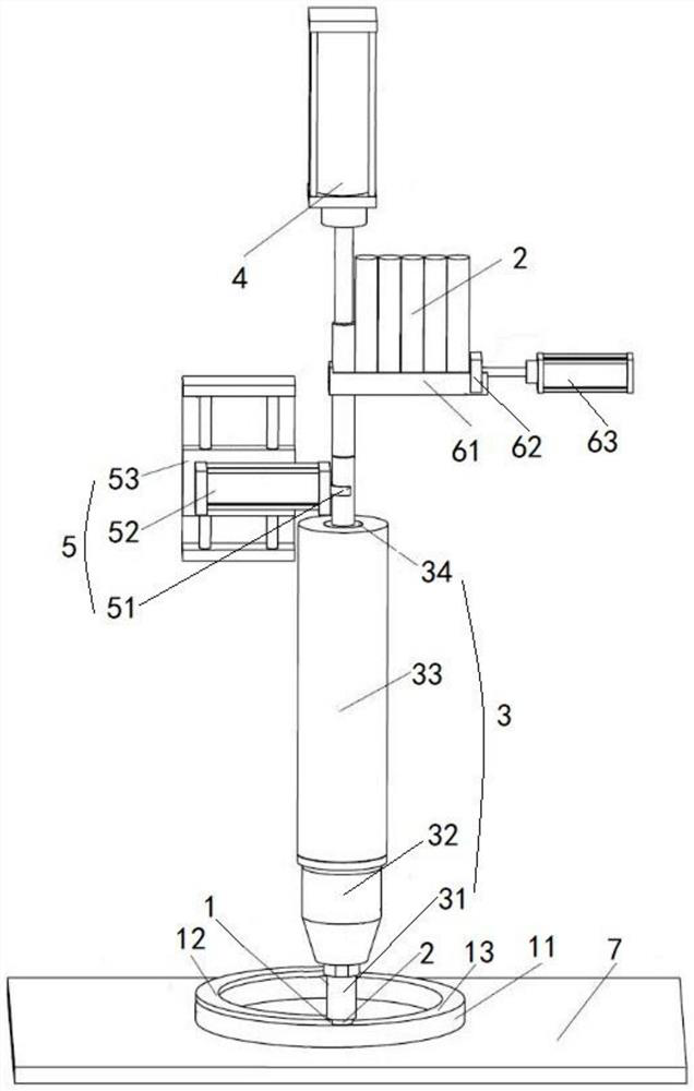
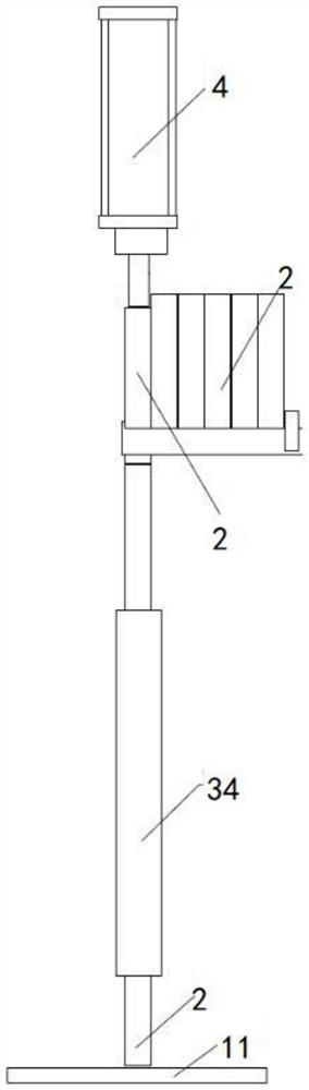
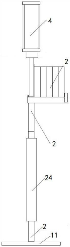
[0039] see Figure 1 to Figure 7 , as shown in the legend, a friction stir welding additive manufacturing device that can continuously feed rods, including a welding mechanism 3 that guides the rod 2 to move axially to the additive position at a friction stir additive position 1, is used to drive The first feeding mechanism 4 for the axial movement of the bar 2 to the increasing position, the second feeding mechanism 5 for driving the axial movement of the bar 2 to the increasing position, and the second feeding mechanism 5 for driving the bar 2 to the side of the first feeding mechanism 4 To the moving feeding mechanism 6, the above-mentioned second feeding mechanism 5 is located between the above-mentioned welding mechanism 3 and the above-mentioned first feeding mechanism 4 and is positioned at the side of the axially moving rod 2, and the above-mentioned feeding mechanism 6 is located at the above-mentioned first Between a feeding mechanism 4 and the above-mentioned second...
PUM
| Property | Measurement | Unit |
|---|---|---|
| diameter | aaaaa | aaaaa |
| length | aaaaa | aaaaa |
| thickness | aaaaa | aaaaa |
Abstract
Description
Claims
Application Information