Additive stirring head with small shaft shoulder acting area and high specific surface area stirring needle

A technology with high specific surface area and stirring needle, used in manufacturing tools, metal processing equipment, welding equipment, etc., can solve problems such as inability to meet friction stir welding, reduce adverse effects, reduce groove size, and increase welding. The effect of closing the width

Active Publication Date: 2022-04-26
YANSHAN UNIV
View PDF7 Cites 3 Cited by
  • Summary
  • Abstract
  • Description
  • Claims
  • Application Information

AI Technical Summary

Problems solved by technology

It can be seen that this kind of stirring head can not meet the needs of multi-layer multi-pass friction stir welding.

Method used


Image

  • Additive stirring head with small shaft shoulder acting area and high specific surface area stirring needle
  • Additive stirring head with small shaft shoulder acting area and high specific surface area stirring needle
  • Additive stirring head with small shaft shoulder acting area and high specific surface area stirring needle

Examples


Embodiment 4

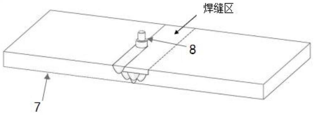
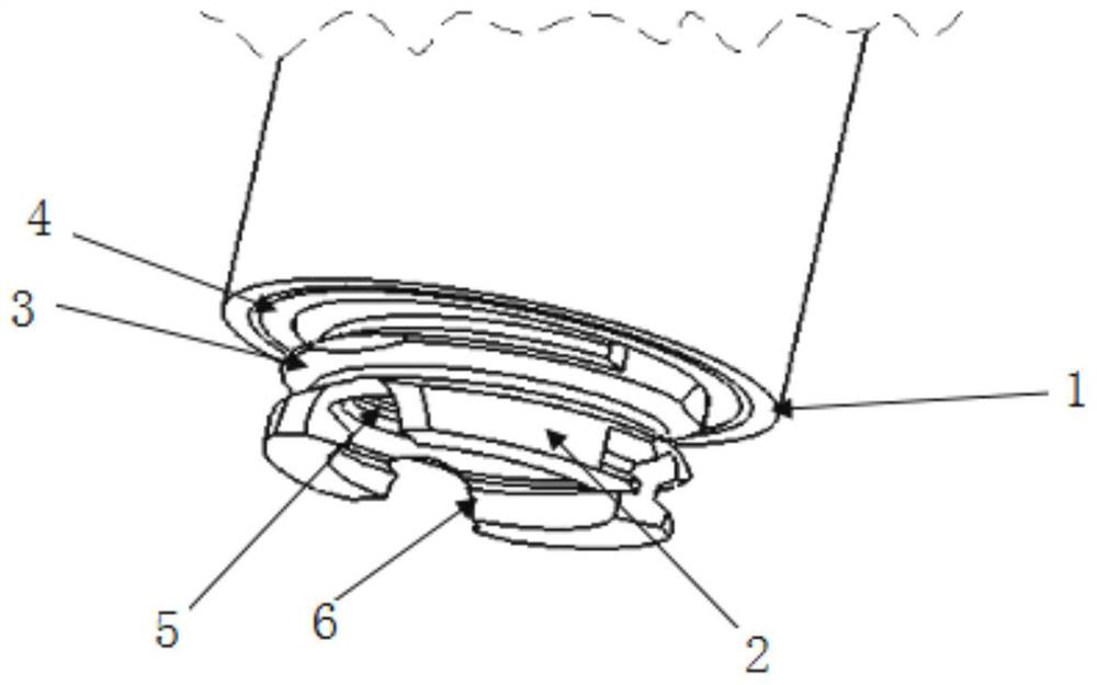
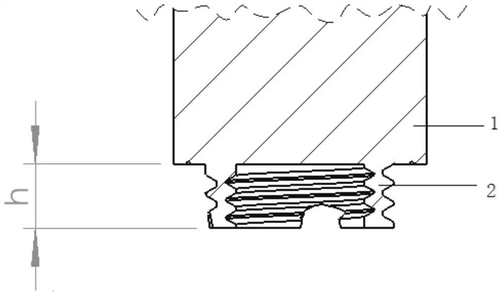
[0036] Embodiment 4, using the stirring head in Embodiment 3 to weld a 5083 aluminum alloy plate with a thickness of 5 mm. The diameter of the shoulder 1 of the stirring head is D=8mm, the diameter of the stirring needle 2 is d=6mm, α=60°, and the length of the stirring needle 2 is 3mm. The rotation speed of the stirring head is 800 rpm, and the travel speed is 30 mm / min. The obtained weld nugget morphology is as follows Figure 5 shown. Depend on Figure 5 It can be seen that the cross-section shape of the obtained nugget area is approximately a regular rectangle, the width is slightly larger than the diameter of the stirring needle 2 , and the height is slightly longer than the length of the stirring needle 2 .

Embodiment 5

[0037] Example 5, using the stirring head in Example 3 to weld a 5mm thick 5083 aluminum alloy plate. Set the diameter of the stirring head shoulder 1 to D=10mm, the diameter of the stirring needle 2 to d=7.5mm, α=60°, and the length of the stirring needle 2 to h=3.8mm. The rotation speed of the stirring head is 800 rpm, and the travel speed is 30 mm / min. The obtained weld nugget morphology is as follows Figure 6 shown. Depend on Figure 6 It can be seen that the cross-section shape of the obtained nugget area is approximately a regular rectangle, the width is slightly larger than the diameter of the stirring needle 2 , and the height is slightly longer than the length of the stirring needle 2 .

Embodiment 6

[0038] Example 6, using the stirring head in Example 3 to weld a 5083 aluminum alloy plate with a thickness of 5 mm. Set the diameter of the stirring head shoulder 1 to D=10mm, the diameter of the stirring needle 2 to d=7.5mm, α=60°, and the length of the stirring needle 2 to h=3.8mm. The rotation speed of the stirring head is 800 rpm, and the travel speed is 60 mm / min. The obtained weld nugget morphology is as follows Figure 7 shown. Depend on Figure 7 It can be seen that the cross-sectional shape of the obtained nugget area is approximately a regular rectangle, the width is slightly larger than the diameter of the stirring pin 2 , and the height is equivalent to the length of the stirring pin 2 .


PUM


Abstract

The invention discloses an additive stirring head with a small shaft shoulder acting area and a high-specific-surface-area stirring needle, and relates to the technical field of metal welding. Comprising a clamping part, a shaft shoulder and a stirring needle which are sequentially connected, and the ratio of the diameter of the stirring needle to the diameter of the shaft shoulder is 0.6-0.8; the ratio of the volume to the surface area of the stirring needle is 2.5-3.5, a cylindrical first groove is formed in the end, away from the shaft shoulder, of the stirring needle in the axis direction of the stirring needle, and spiral flow guide grooves are formed in the outer circumferential face of the stirring needle and the inner circumferential face of the first groove. The method is used for reducing lap joint passes and can avoid the problem that interfaces of all layers are not welded.

Description

technical field [0001] The present application relates to the technical field of metal welding, in particular to a stirring head for additives with a small shoulder action area and a high specific surface area stirring needle. Background technique [0002] In recent years, based on the urgent need for lightweight structures in the fields of aviation, ships, military equipment, and rail transit, the welding of light alloys such as large thickness (≥15mm) high-performance aluminum and magnesium has become a key technology that must be solved. Metallurgical defects such as hot cracks and pores are very easy to be welded by traditional fusion welding methods. Friction stir welding technology is considered to be the most effective method for welding such alloys at present. [0003] However, although the single-sided or double-sided large-thickness friction stir welding process has been used at home and abroad to achieve welding of aluminum alloys with a joint thickness of up to 1...

Claims


Application Information

Patent Timeline
Patent Type & Authority Applications(China)
IPC IPC(8): B23K20/26B23K20/12
CPCB23K20/26B23K20/12
Inventor 付瑞东李艺君雷雨
Owner YANSHAN UNIV
Why Eureka
Try Eureka