Metal part heat treatment process

A technology of metal parts and heat treatment devices, which is applied in the field of heat treatment, can solve the problems of low production efficiency, inability to replace quenching liquid, and affect the effect of heat treatment, etc., to achieve the effect of improving safety, improving functionality, and improving convenience

Inactive Publication Date: 2022-04-26
张站群
View PDF1 Cites 1 Cited by
  • Summary
  • Abstract
  • Description
  • Claims
  • Application Information

AI Technical Summary

Problems solved by technology

[0003] For example, in the heat treatment process of metal parts in the publication number CN202011570801.3, the heat-treated metal gears are usually directly sprayed with water to cool them, so as to avoid the cracks of the metal gears caused by the sudden temperature change of the metal gears. The device cools metal gears of different specifications after heat treatment, thereby improving the applicability of the equipment and reducing the production cost and efficiency of metal gears; by manually pulling the clamping shaft to the outside, the clamping shaft moves up along the rotating block, and through The locking spring squeezes and rotates the locking plate to move outward, so that the clamping shaft and the rotating locking plate can clamp and fix the metal gears of different thickness specifications. After the metal gears are heat-treated, manually pull the pull rod upwards so that the pull rod passes through the wire rope to the inside Pull and rotate the locking plate to gather it inside the clamping shaft, so as to remove and collect the heat-treated metal gears; the inserted rod is snapped into the adjustment holes at different positions, so that the sliding plate can quickly adjust the position of the nozzle, so that the nozzle Cooling treatment of metal gears of different sizes; although the above device can perform uniform heat treatment on metal gears of different sizes when in use, cooling the parts directly through the nozzle will affect the heat treatment effect, and the quenching liquid cannot be cooled during the quenching process. Replacement, and the existing heat treatment device needs to interrupt the quenching work when replacing the quenching liquid, resulting in low production efficiency

Method used


Image

  • Metal part heat treatment process
  • Metal part heat treatment process
  • Metal part heat treatment process

Examples


Embodiment

[0038] In order to make the purpose, technical solution and advantages of the present invention clearer, the following will further describe the implementation of the present invention in detail in conjunction with the accompanying drawings.

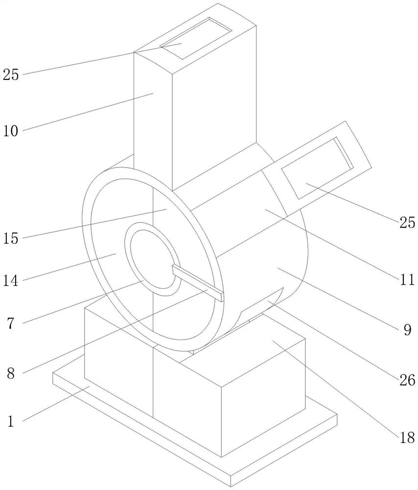
[0039] Such as Figure 1-7 Shown, a metal parts heat treatment process, comprising the following steps:

[0040]A. Adding liquid: by adding quenching liquid to the interior of the metal parts heat treatment device, the preparation work before heat treatment and quenching is completed;

[0041] B. Quenching the workpiece: through the suspension device, the metal parts are lowered into the quenching liquid for quenching heat treatment;

[0042] C. Automatic replacement of quenching liquid: to replace the quenching liquid, discharge the used quenching liquid at the same time, and then automatically add the quenching liquid to the empty box;

[0043] D. Protect the heat treatment device of metal parts: In the process of replacing the quenc...


PUM


Abstract

The invention belongs to the technical field of heat treatment, and particularly relates to a metal part heat treatment process which comprises the following steps: A, liquid adding: adding quenching liquid into a metal part heat treatment device to finish preparation work before heat treatment quenching; b, quenching the workpiece: descending the metal part into quenching liquid through a suspension device for quenching heat treatment; c, the quenching liquid is automatically replaced, specifically, the quenching liquid is replaced, the used quenching liquid is discharged during replacement, and then the quenching liquid is automatically added into the empty box body; d, the metal part heat treatment device is protected, specifically, in the process of replacing the quenching liquid, the device can slowly adjust the positions of box bodies on the left side and the right side through gradual rotation of a driving device; according to the metal part heat treatment device, a rotating shaft of a motor can play a buffering role in the forward rotation and reverse rotation processes through a vortex spring in the metal part heat treatment device, and quenching liquid can be automatically replaced by the device through a communication structure between a first inner shell and a second inner shell.

Description

technical field [0001] The invention relates to the technical field of heat treatment, in particular to a heat treatment process for metal parts. Background technique [0002] The main purpose of heat treatment is to eliminate the internal stress of metal parts, thereby improving the overall strength of metal parts. When performing heat treatment on metal parts, it is necessary to use a quenching device for heat treatment. The existing quenching devices still have some defects in use. [0003] For example, in the heat treatment process of metal parts in the publication number CN202011570801.3, the heat-treated metal gears are usually directly sprayed with water to cool them, so as to avoid the cracks of the metal gears caused by the sudden temperature change of the metal gears. The device cools metal gears of different specifications after heat treatment, thereby improving the applicability of the equipment and reducing the production cost and efficiency of metal gears; by m...

Claims


Application Information

Patent Timeline
Patent Type & Authority Applications(China)
IPC IPC(8): C21D1/18C21D1/64C21D9/00
CPCC21D1/18C21D1/64C21D9/0062
Inventor 张站群
Owner 张站群
Why Eureka
Try Eureka