Control method of temperature control system and temperature control system

A technology of a temperature control system and a control method, applied in the control of temperature control systems and the field of temperature control systems, can solve the problems of affecting the temperature control effect, mutual interference, periodic oscillation of temperature control, etc., to achieve simple and accurate temperature control, reduce complexity degree, the effect of the realization of the control plan

Pending Publication Date: 2022-04-26
BEIJING JINGYI AUTOMATION EQUIP CO LTD
View PDF8 Cites 0 Cited by
  • Summary
  • Abstract
  • Description
  • Claims
  • Application Information

AI Technical Summary

Problems solved by technology

[0005] The present invention provides a control method of a temperature control system and a temperature control system, which are used to solve the problem that the temperature control system in the prior art may interfere with each other through two independent PID adjustments, affect the temperature control effect, or cause coupling to cause temperature control. The defect of periodic oscillation realizes the simplification of the control scheme, and also reduces the problem of periodic oscillation of the outlet temperature caused by the coupling of two sets of PIDs. The compressor output ratio of the high and low temperature stage system is the same, which ensures the simultaneous Reaching the maximum output state ensures that the entire cascade refrigeration system can exert the maximum output

Method used


Image

  • Control method of temperature control system and temperature control system
  • Control method of temperature control system and temperature control system

Examples


Embodiment Construction

[0042] Embodiments of the present invention will be further described in detail below in conjunction with the accompanying drawings and examples. The following examples are used to illustrate the present invention, but should not be used to limit the scope of the present invention.

[0043] In the description of the embodiments of the present invention, it should be noted that the terms "center", "longitudinal", "transverse", "upper", "lower", "front", "rear", "left", "right" , "vertical", "horizontal", "top", "bottom", "inner", "outer" and other indicated orientations or positional relationships are based on the orientations or positional relationships shown in the drawings, and are only for the convenience of describing this The embodiments and simplified descriptions of the invention do not indicate or imply that the devices or elements referred to must have a specific orientation, be constructed and operate in a specific orientation, and therefore should not be construed a...


PUM


Abstract

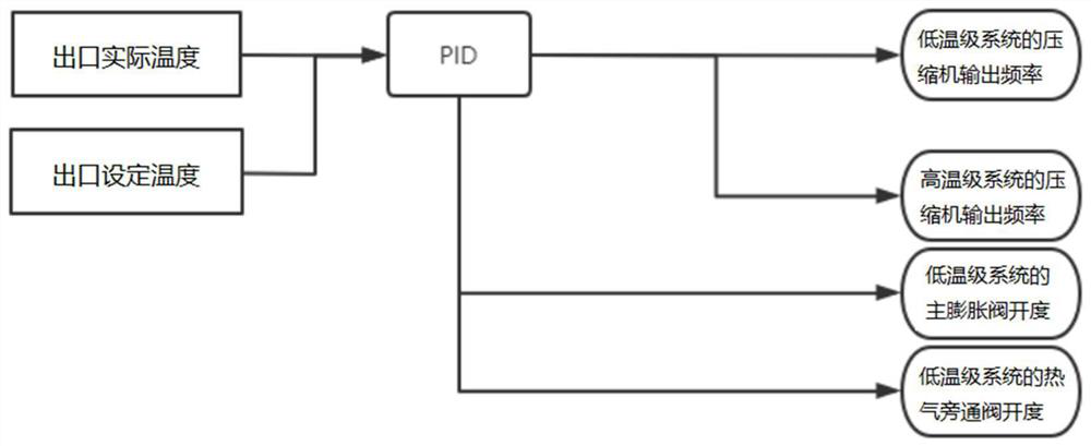
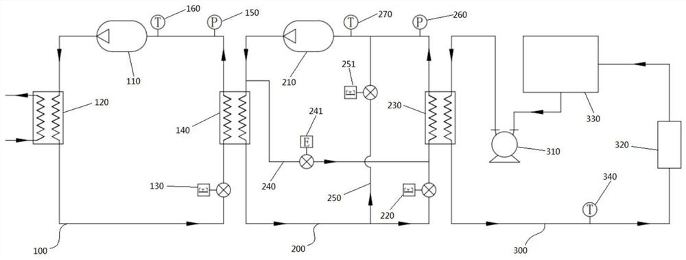
The invention relates to the technical field of semiconductor production, in particular to a control method of a temperature control system and the temperature control system.The control method of the temperature control system comprises the steps that the actual temperature value of an outlet of the temperature control system is obtained; and according to the target temperature value and the actual temperature value of the outlet of the temperature control system, the output frequency of the compressor of the low-temperature-stage system and the output frequency of the compressor of the high-temperature-stage system are controlled. A set of PID algorithm is used, the output percentage of the compressors of the high-temperature-level system and the low-temperature-level system is controlled at the same time, the control complexity is reduced, the control scheme is simplified, the problem that the outlet temperature is periodically oscillated due to coupling of the two sets of PID is solved, mutual interference of the high-temperature-level system and the low-temperature-level system is avoided, and the control efficiency is improved. Accurate temperature control of the cascade refrigeration system is simply realized. Meanwhile, the compressor output ratios of the high-temperature stage system and the low-temperature stage system are the same, it is guaranteed that the high-temperature stage system and the low-temperature stage system reach the maximum output state at the same time, and it is guaranteed that the whole cascade refrigeration system can exert the maximum output.

Description

technical field [0001] The invention relates to the technical field of semiconductor production, in particular to a control method of a temperature control system and the temperature control system. Background technique [0002] In the current semiconductor memory chip manufacturing process, multi-layer stacking is the current mainstream research and development direction, and its process characteristics require a higher aspect ratio in the etching process. A well-controlled aspect ratio requires a lower constant ambient temperature during the etching process. At present, the domestic advanced 3D NAND process requires a temperature of -70°C for the etching process. At present, the mainstream temperature control system for semiconductors is to use conventional The advanced R404a / R23 cascade refrigeration system realizes low temperature control. During the etching process, there are two main difficulties for the temperature control system to control the constant temperature: ...

Claims


Application Information

Patent Timeline
Patent Type & Authority Applications(China)
IPC IPC(8): F25B7/00F25B41/20F25B41/385F25B41/40F25B49/02
CPCF25B7/00F25B49/02F25B49/022F25B41/20F25B41/385F25B41/40F25B2600/021F25B2600/2501
Inventor 刘紫阳胡文达靳李富李文博芮守祯曹小康董春辉
Owner BEIJING JINGYI AUTOMATION EQUIP CO LTD
Why Eureka
Try Eureka