
Joint nursing device based on surgical nursing

A technology for nursing devices and joints, which is applied in the directions of enema/irrigator, infusion set, suction device, etc., can solve the problems of affecting the treatment and care of patients, increasing the pain of patients, suturing the wound and opening the thread, etc., so as to achieve convenient treatment and care. , the effect of prolonging the preparation time and reducing the dripping speed

Pending Publication Date: 2022-04-29
天津市第四中心医院
View PDF10 Cites 0 Cited by
  • Summary
  • Abstract
  • Description
  • Claims
  • Application Information

AI Technical Summary

Problems solved by technology

[0004] During the process of suctioning the silicone tube by the negative pressure suction device, the silicone tube may be blocked due to the blood clot, cellulose membrane and necrotic tissue in the wound of the patient. Medical personnel need to use a syringe to insert the suction tube, and the normal saline in the syringe is sucked through the suction tube. The tube recoils against the affected area, thereby pushing the blockage away from the mouth of the silicone tube, so that the patient's joint cavity is in a state of communication. The medical staff can determine whether the suction tube and the joint cavity are blocked by observing the swelling of the patient's wound. When the wound starts to bulge, it is necessary to recoil the wound of the patient. However, when the suction tube is blocked, the patient is in a sleeping position and cannot observe the wound bulge in time. The medical staff may temporarily leave the ward due to work, which may cause the patient’s wound to be sutured The skin bulge at the position is larger, which increases the pain of the patient. In severe cases, it may cause the stitches to open at the sutured wound, which affects the treatment and nursing of the patient. Therefore, we propose a joint care device based on surgical care.

Method used


Image

  • Joint nursing device based on surgical nursing
  • Joint nursing device based on surgical nursing
  • Joint nursing device based on surgical nursing

Examples


Embodiment Construction

[0031] The following will clearly and completely describe the technical solutions in the embodiments of the present invention with reference to the accompanying drawings in the embodiments of the present invention. Obviously, the described embodiments are only some, not all, embodiments of the present invention. Based on the embodiments of the present invention, all other embodiments obtained by persons of ordinary skill in the art without making creative efforts belong to the protection scope of the present invention.

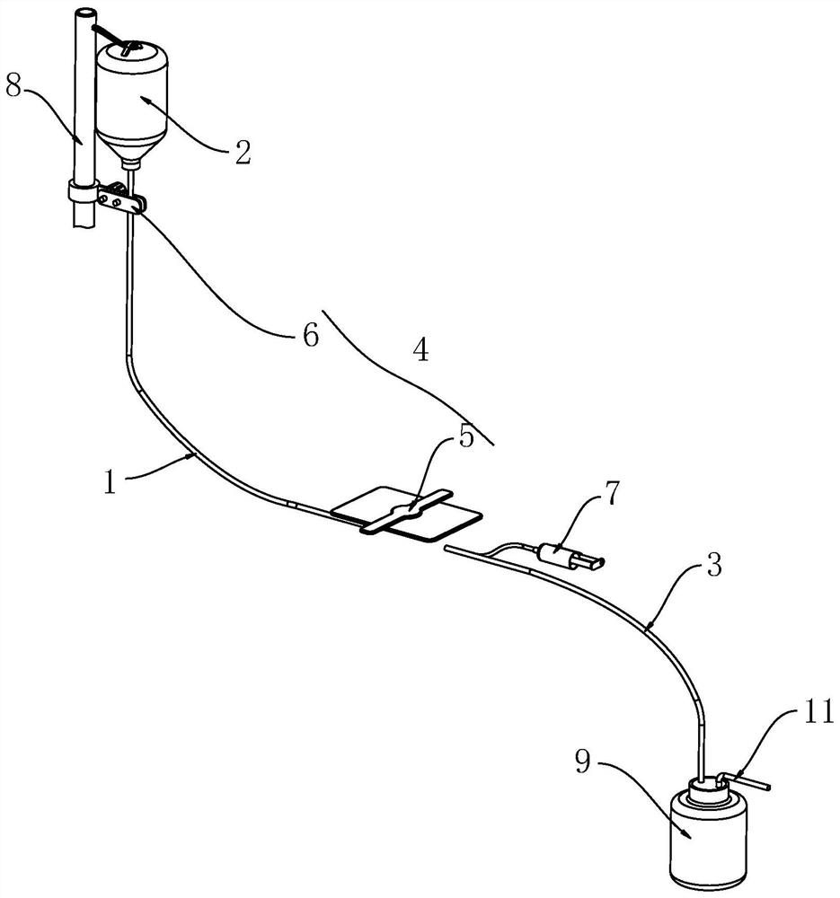
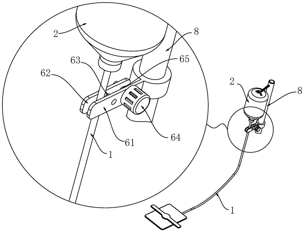
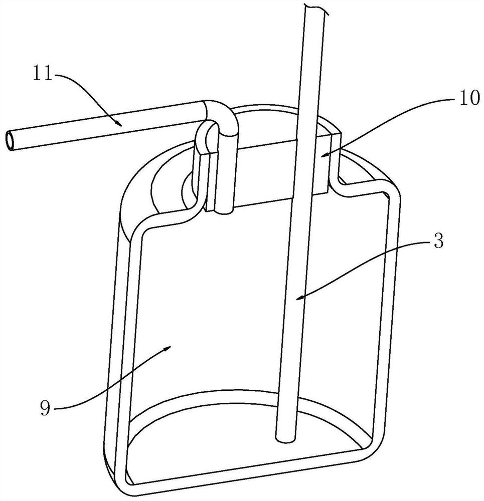
[0032] see Figure 1-10 , the present invention provides a technical solution: a joint care device based on surgical care, comprising:

[0033] Dropper 1, one end of the dropper 1 is connected with a lavage bottle 2, the dropper 1 is inserted into the lavage bottle 2, the height of the lavage bottle 2 is higher than the height of the patient's wound, and the dropper 1 is inserted into the In the patient's wound skin (14);

[0034] Suction tube 3, the suction...


PUM


Abstract

The invention discloses a joint nursing device based on surgical nursing, which comprises a dropper, one end of the dropper is connected with a lavage bottle, the lavage bottle is higher than the wound of a patient, and the dropper is inserted into the skin of the wound of the patient; the suction tube is inserted into the wound of the patient, and the suction tube and the dropper are distributed in parallel relatively; the dredging mechanism is installed on the outer side of the dropper and the outer side of the suction tube, and the dredging mechanism reduces the dripping speed of the dropper when the wound of the patient is blocked, the dripping speed of the dropper can be reduced in time through the transmission mechanism, and medical staff can conveniently handle blocking in time when returning to a ward; in addition, when the medical staff does not carry out manual back-flushing treatment in time, the air cylinder can automatically push normal saline to carry out back-flushing, then the possibility that the wound of the patient is torn is reduced, and treatment and nursing of the patient are facilitated.

Description

technical field [0001] The invention relates to the technical field of joint care, in particular to a joint care device based on surgical care. Background technique [0002] The connection between bones is called bone connection. Bone connection is divided into direct connection and indirect connection. Joint is a form of indirect connection. Suppurative bone and joint infection is a kind of joint disease. Medical staff treat it It needs to be surgically cut open at the joint position before treatment. [0003] Wound closure irrigation and suction method is a kind of postoperative treatment and nursing for patients. Some patients need to use wound closure irrigation and suction method to care for joints after resection of the lesion. Place two silicone tubes facing each other in parallel. One of the silicone tubes is used as a drip tube and connected to the irrigation bottle. By placing antibiotics in the irrigation bottle, the drip tube drips the antibiotic solution into t...

Claims


Application Information

Patent Timeline
Patent Type & Authority Applications(China)
IPC IPC(8): A61M3/02A61M1/00
CPCA61M3/0279A61M2205/18A61M2205/3334A61M2205/3331
Inventor 鲁欣李育欣
Owner 天津市第四中心医院
Learn More