Puncture template based on optical positioning, auxiliary radiotherapy constant force tracking system realized by applying same, and constant force tracking method

An optical positioning and puncture template technology, which is applied in X-ray/γ-ray/particle irradiation therapy, etc., can solve the problems of uneven weight distribution of 3D printing templates, difficulty in tracking optical balls, and inability to track with constant force. The effect of high force tracking accuracy, easy maintenance and easy operation

Active Publication Date: 2022-04-29
HARBIN INST OF TECH
View PDF7 Cites 0 Cited by
  • Summary
  • Abstract
  • Description
  • Claims
  • Application Information

AI Technical Summary

Problems solved by technology

[0005] The purpose of the present invention is to solve the existing problems of uneven weight distribution based on 3D printing templates, easy deviation, difficult operation, difficult tracking of optical balls, and inability to track them with constant force. The present invention provides a Puncture template based on optical positioning, and constant force tracking system and constant force tracking method for auxiliary radiotherapy realized by applying the template

Method used


Image

  • Puncture template based on optical positioning, auxiliary radiotherapy constant force tracking system realized by applying same, and constant force tracking method
  • Puncture template based on optical positioning, auxiliary radiotherapy constant force tracking system realized by applying same, and constant force tracking method
  • Puncture template based on optical positioning, auxiliary radiotherapy constant force tracking system realized by applying same, and constant force tracking method

Examples


specific Embodiment approach 1

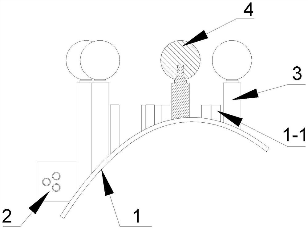
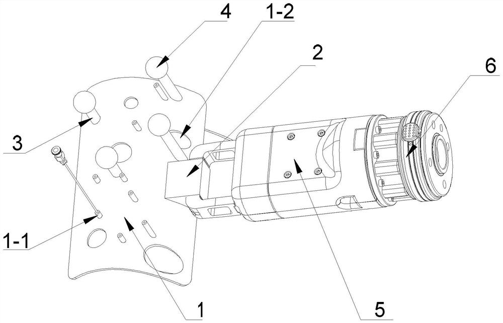
[0029] Specific implementation mode one: the following combination figure 1 with figure 2 Describe this embodiment. The puncture template based on optical positioning described in this embodiment includes a 3D printing template 1 and a clamping connector 2, and also includes N positioning reference columns 3 and N optical balls 4; N is an integer;

[0030] The clamping connector 2 is fixed at the middle part of the lower end of the 3D printing template 1;

[0031] The 3D printing template 1 is a curved surface structure, and a plurality of puncture needle tracks 1-1 are arranged on it;

[0032] N positioning reference columns 3 are fixed on the upper surface of the 3D printing template 1, and an optical ball 4 is fixed on the top of each positioning reference column 3;

[0033] The middle part of the lower end of the 3D printing template 1 is provided with a clamping connector 2 , and the clamping connector 2 is used for fixed connection with the clamping jaw 5 on the mecha...

specific Embodiment approach 2

[0035] Specific implementation mode two: the following combination figure 1 with figure 2 This embodiment will be described. This embodiment will further describe the first embodiment. The upper surface of the 3D printing template 1 is provided with a plurality of hollow holes 1-2.

[0036] In this preferred embodiment, by adding hollow holes 1-2, the weight of the 3D printing template 1 is further reduced, which is convenient for operation. In a specific application, the sizes of the multiple hollow holes 1-2 are different, and the center of mass of the balanced 3D printing template 1 is at the center of the 3D printing template 1 as a reference.

specific Embodiment approach 3

[0037] Specific implementation mode three: the following combination figure 1 This embodiment will be described. This embodiment will further describe the first embodiment. The top end of the positioning reference column 3 and the optical ball 4 are fixed by plugging.

[0038] In this preferred embodiment, the top end of the positioning reference column 3 and the optical ball 4 are fixed through a plugging connection, so that the structure is simple and the assembly and disassembly are convenient.


PUM


Abstract

The invention discloses a puncture template based on optical positioning, an auxiliary radiotherapy constant force tracking system realized by applying the template, and a constant force tracking method, and relates to the field of robot-assisted close-range radiotherapy based on a 3D printing template. The problems that an existing 3D printing-based template is not uniform in weight distribution, deviation is prone to occurring, the operation difficulty is large, the optical ball tracking difficulty is large, and constant-force tracking cannot be conducted on the 3D printing-based template are solved. The puncture template comprises a 3D printing template, a clamping connecting piece, N positioning reference columns and N small optical balls. The clamping connecting piece is fixed to the middle of the lower end of the 3D printing template. The 3D printing template is of a curved surface structure, and a plurality of puncture needle channels are formed in the 3D printing template; the N positioning reference columns are fixed on the upper surface of the 3D printing template, and an optical ball is fixed at the top end of each positioning reference column; a clamping connecting piece is arranged in the middle of the lower end of the 3D printing template. The method is mainly used for performing constant force tracking on the 3D printing template.

Description

technical field [0001] The invention relates to the field of robot-assisted brachytherapy based on 3D printed templates. Background technique [0002] With the development and popularization of robots, more and more industries have begun to use robots to replace manual operations, and various types of robots have begun to appear in people's vision. In recent years, more and more robots have been involved in the medical field, and in surgery, more and more surgeons are using robots to assist when performing operations. [0003] In the prior art, when performing thoracoabdominal brachytherapy particle implantation surgery, there is a navigation device realized by a 3D printed template for particle implantation positioning technology, but in specific applications, there is a problem that the navigation device realized by a 3D printed template has poor application flexibility. Defects, the main manifestations are: the optical ball is fixed on one side of the 3D printing templat...

Claims


Application Information

Patent Timeline
Patent Type & Authority Applications(China)
IPC IPC(8): A61N5/10
CPCA61N5/1002A61N5/1014A61N5/103A61N5/1049A61N2005/1024Y02P10/25
Inventor 李长乐张雷锋范逸伦刘刚峰张学贺赵杰
Owner HARBIN INST OF TECH
Why Eureka
Try Eureka